Mounting and wiring instructions /
Safety relay module
for emergency stop monitoring and guard door monitoring
PROTECT
SRB 200EXi-1R
4
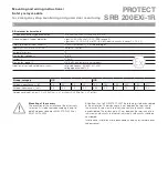
EX-relevant technical data
EC type examination/type examination
TÜV 08 ATEX 7522 / TÜV 08 ATEX 7557 X
Group, category, type of protection
gas:
•
L
II 3 G Ex nAnC IIC T5 (SRB in zone 2)
gas/dust:
•
L
II (2) GD [Ex ib] IIC / [Ex ibD] (electric circuits in zones 1, 21/2, 22)
Safety-related maximum current U
m
253 VAC (Attention: U
m
is’nt rated voltage!)
Inputs (S11-S12, S21-S22, X1-X3)
[Ex ib] IIC / [Ex ibD]
Temperature class
T5
Max. output voltage U
o
33.6 V
Current I
o
57.0 mA
Max. output power P
o
478.8 mW (characteristic curve linear)
Isolation (intrinsically safe/other circuits)
safe isolation acc. EN 60 079-11:2007,
voltage peak value 375 V
Group, category
II C
II B
External capacitance C
o
(nF)
26
36
46
49
160
180
230
280
350
412
External inductance L
o
(mH)
4.0
2.0
1.0
0.5
38.0
5.0
2.0
1.0
0.5
0.2
Reference value of a circuit: C ≈ 200 nF/km, L ≈ 1 mH/km (C ≈ 200 pF/m, L ≈ 1 µH/m)
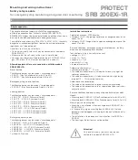
Mounting of the sensors
The execution of the installation of the intrinsically
safe circuits is to be realized according the up-to-
date European standards EN 60 079-14:2003 or
EN 61 241-14:2004.
Attention:
Acc. to EN 60 079-11:2007 the following is to be considered
at the installation: The distance of ≥ 6 mm between the terminals of
the intrinsically safe circuits to other intrinsically safe circuits should
be considered. The distance of ≥ 50 mm between the terminals of the
intrinsically safe circuits to other not intrinsically safe circuits should be
considered.
Initiation and installation are to be accomplished only by therefore quali-
fied personnel.


