PROTECT
SRB 200EXi-1R
Mounting and wiring instructions /
Safety relay module
for emergency stop monitoring and guard door monitoring
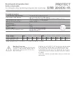
5
U
EXi
U
B
U
i
K1
K2
SRB
200EXi
-1R
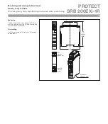
0V X1 X2
S11 S12 S21 S22
13 14 23 24
PA PA A1 A2
2
s
1,5 mm
2
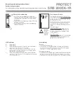
Special terms for use in zone 2
Installation in Zone 2
The units are to be installed in switching or junction boxes, which
•
consider the terms of EN 60 079-15:2005.
The unit may only be installed and operated by personnel who are
•
familiar with both these instructions and the current regulations for
safety at work and accident prevention.
The intrinsically safe circuits of the unit (light blue terminals) may
•
be layed in explosion-endangered areas. In this procedure there is
to pay attention to a safe disconnection to all not intrinsically safe
circuits.
Attention:
Connecting and disconnecting of contacts of not intrinsically safe
•
circuits under potentially explosion atmosphere is not allowed.
The housing may only be cleaned with a wet cloth.
•
The life cycle of the module, relating to the type of protection “nC“, is
•
at least 15 years. After end of this time the module is to be changed
or to be send to the manufacturer for a check-up!
Attention:
The temperature declarations (–25 °C ≤ Ta ≤ + 60 °C) of the module
•
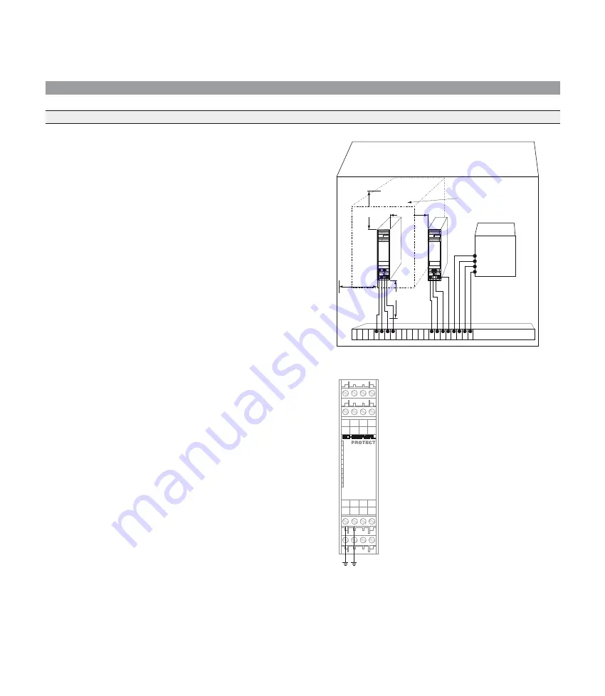
refer to a minimum volume of the switching box of approx. 2,400 cm
3
per SRB. Make sure you maintain a distance of approx. 5 cm to other
sub-assemblies.
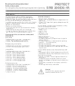
5 cm
Switching box IP 54
qualified for installation in zone 2
acc. EN 60079-15
Air about the module
approx. 2,400 cm
3
(8.25
s
16
s
18.1 cm)
Contactor
II 3G
Terminals (Cl. II 3G)
5 cm
5 cm
5 cm
Potential equalisation
Connection of the PA terminals
Acc. EN 60 079-14:2003 Clause 12.2.4 two
•
conductors with a cross section of at least
1.5 mm
2
may be connected between the
terminals PA and the potential equalisation.


