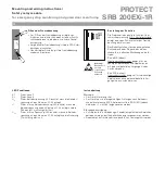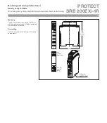
PROTECT
SRB 200EXi-1R
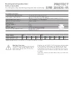
Mounting and wiring instructions /
Safety relay module
for emergency stop monitoring and guard door monitoring
9
X1 X2
23
13
24
14
K
A
K
D
S
L1
N
K
B
K
C
K
D
K
A
X1 X2
23
13
24
14
K
A
K
B
S
L1
N
K
A
K
B
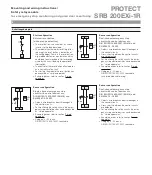
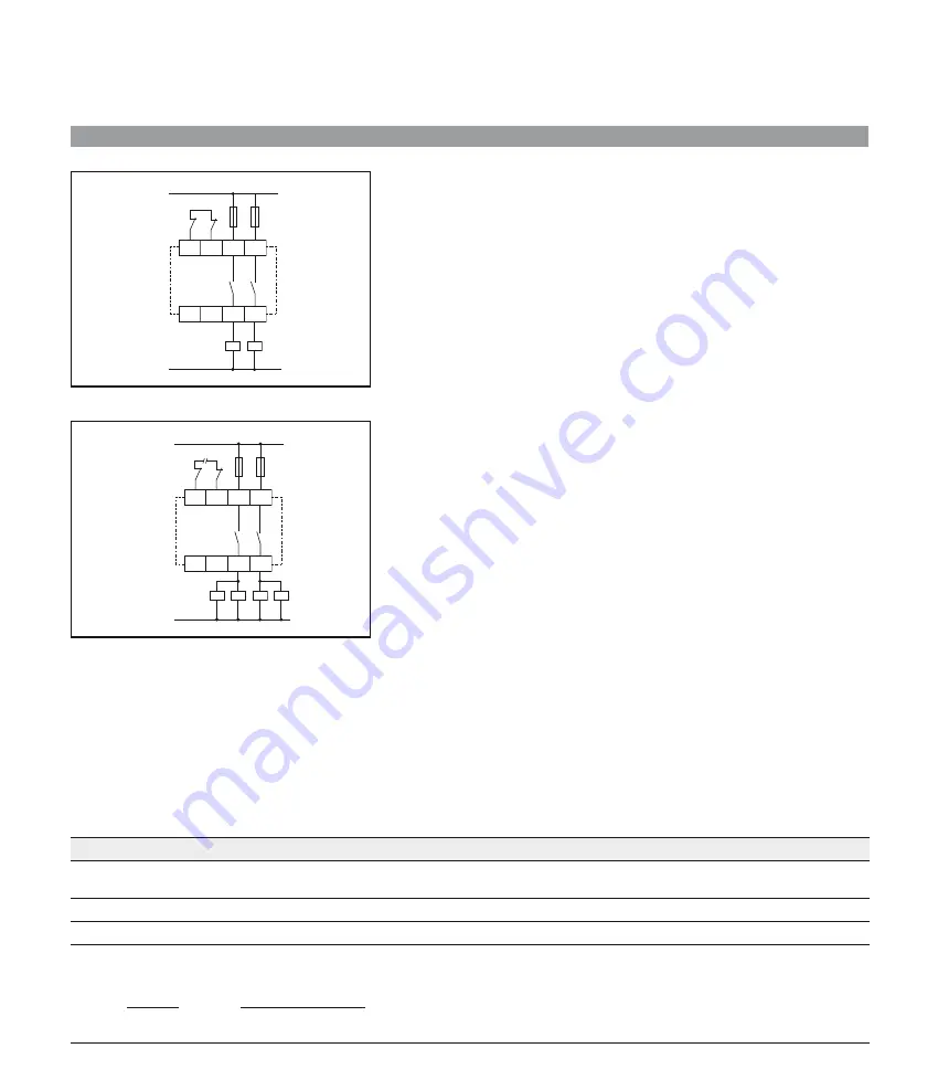
Actor configuration
Dual-channel control with feedback loop
Suitable for contact amplification or contact multiplication by means of relays or con-
•
tactors with positively opening contacts.
If the feedback is not required it is to be replaced by a bridge.
•
Attention:
•
Acc. to EN 60 079-11:2007 the following is to be considered at the instal-
lation: The distance of ≥ 6 mm between the terminals of the intrinsically safe circuits
to other intrinsically safe circuits should be considered. The distance of ≥ 50 mm
between the terminals of the intrinsically safe circuits to other not intrinsically safe
circuits should be considered.
The phasing of the enabling paths (13-14/23-24) may not be different, i.e. only one
•
phase may be connected to both terminals.
S
= Feedback loop
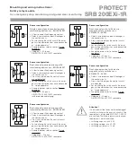
Actor configuration
Single-channel control with feedback loop
Suitable for contact amplification or contact multiplication by means of relays or con-
•
tactors with positively opening contacts.
If the feedback is not required it is to be replaced by a bridge.
•
Attention:
•
Acc. to EN 60 079-11:2007 the following is to be considered at the instal-
lation: The distance of ≥ 6 mm between the terminals of the intrinsically safe circuits
to other intrinsically safe circuits should be considered. The distance of ≥ 50 mm
between the terminals of the intrinsically safe circuits to other not intrinsically safe
circuits should be considered.
The phasing of the enabling paths (13-14/23-24) may not be different, i.e. only one
•
phase may be connected to both terminals.
S
= Feedback loop
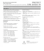
Function description
The SRB 200EXi-1R is a dual-channel safety relay module for the monitoring of emergency stop control devices, guard monitoring and safety
•
magnet switches.
In the case of closed protection circuits S11-S12 and S21-S22 and closed feedback loop X1-X2 the module starts up after activating and releas-
•
ing and close the enabling paths 13-14/23-24.
By actuation of the emergency stop control device or an other protection device the enabling paths 13-14/23-24 will be opened directly.
•
The module can be restarted when both internal relays K1 and K2 have been dropped out.
•
Data within the meaning of DIN EN ISO 13 849-1:2007
B
10d
value (for one channel)
with low load: 20,000,000
•
with maximum load: 400,000
•
DC (internal error detection)
99% (high)
CCF
> 65 points
Conversion in MTTF
d
: refer to
DIN EN ISO 13 849-1:2007 Annex C Item C.4.2
MTTF
d
=
B
10d
n
op
=
d
op
× h
op
× 3,600 s/h
0.1 × n
op
t
cycle
d
op
= average number of operating day per year
h
op
= average number of operating hours per day
t
cycle
= average request of the safety function in s
(for example 4 × per hour = 1 × per 15 min. = 900 s)


