Installation manual
Page 106 of204
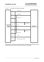
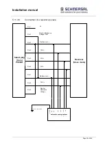
5.12.2.7
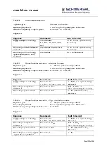
HTL - Sensor
Signal level.
24V/0V
Physical Layer:
Push/Pull
Measuring signal A/B
track with 90° phase difference
Max. counting pulse frequency:
200 kHz on X27/28 or X29/30
(only PSCBR-C-10-SDM1/2)
Diagnoses:
Diagnose
Parameters
Fault threshold
Supply voltage monitoring
Fixed values
5 V, 8V, 10V, 12V, 20V, 24V
+/- 20 % +/-2 %(measuring
tolerance)
Monitoring of differential level
on input
Fixed value 24 V
+/- 20 % +/-2 %(measuring
tolerance)
Monitoring of the counting
signal separated for each
track A/B
Fixed value
DP > 4 increments
5.12.2.8
Resolver
Measuring signal:
SIN/COS
– track with 90° phase difference
Max. counting pulse frequency
2 kHz/pole
Resolution:
9 bit / pole
Master-Mode:
Frequency reference signal
8 kHz
Slave-Mode
Frequency reference signal
6 - 16 kHz
Reference signal form:
Sinusoidal, triangle
1)
on X31/32
2)
on X31/34
Diagnoses:
Diagnose
Parameters
Fault threshold
Monitoring of ratio
Fixed values
2:1, 3:2, 4:1
+/- 20 % +/-2 %(measuring
tolerance)
Monitoring of signal
amplitude SIN²+COS²
Fixed value
<2.8 V +/-5 % (measuring
tolerance)
Monitoring of phases A/B
Fixed value 90°
+/- 7° +/-2°(measuring
tolerance)
Monitoring of reference
frequency
Fixed values
6 .. 12 kHz in steps of 1 kHz,
14 kHz, 16 kHz
+/- 20 % +/-5 %(measuring
tolerance)
Form of reference signal
Sinusoidal, triangle, no
monitoring
40 % form deviation
Monitoring of counting signal
/ signal phase quadrant
Fixed value
+/- 45°
Summary of Contents for PSCBR-C-10 Series
Page 1: ...Installation manual Page 1 of204 Installation Manual For PSCBR modules Series PSCBR C 10...
Page 178: ...Installation manual Page 178 of 204...
Page 181: ...Installation manual Page 181 of 204 Example for a risk analysis Gefahrenanalyse Risk analysis...

