Installation manual
Page 128 of204
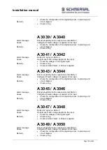
Remedy
Check the configuration of the digital input acc. to planning and
circuit diagram
Check wiring
A 3039 / A 3040
Alarm message
Pulse2 plausibility fault on expansion inlet EAEx.2
Cause
Configured Pulse2 voltage not applied to this input.
Remedy
Check the configuration of the digital input acc. to planning and
circuit diagram
Check wiring
A 3041 / A 3042
Alarm message
Faulty 24V signal on EAEx.2
Cause
No permanent 24V voltage applied to this input
Remedy
Check the voltage on the digital input!
Check wiring
Check whether Pulse1 or Pulse2 is applied
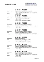
A 3043 / A 3044
Alarm message
Pulse1 plausibility fault on expansion inlet EAEx.3
Cause
Configured Pulse1 voltage not applied to this input.
Remedy
Check the configuration of the digital input acc. to planning and
circuit diagram
Check wiring
A 3045 / A 3046
Alarm message
Pulse2 plausibility fault on expansion inlet EAEx.3
Cause
Configured Pulse2 voltage not applied to this input.
Remedy
Check the configuration of the digital input acc. to planning and
circuit diagram
Check wiring
A 3047 / A 3048
Alarm message
Faulty 24V signal on EAEx.3
Cause
No permanent 24V voltage applied to this input
Remedy
Check the voltage on the digital input!
Check wiring
Check whether Pulse1 or Pulse2 is applied
A 3049 / A 3050
Alarm message
Pulse1 plausibility fault on expansion inlet EAEx.4
Cause
Configured Pulse1 voltage not applied to this input.
Remedy
Check the configuration of the digital input acc. to planning and
circuit diagram
Check wiring
Summary of Contents for PSCBR-C-10 Series
Page 1: ...Installation manual Page 1 of204 Installation Manual For PSCBR modules Series PSCBR C 10...
Page 178: ...Installation manual Page 178 of 204...
Page 181: ...Installation manual Page 181 of 204 Example for a risk analysis Gefahrenanalyse Risk analysis...


