Installation manual
Page 166 of204
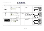
13 Switch types
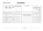
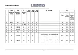
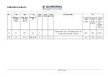
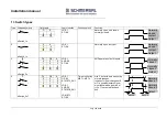
Type Graphic symbols
Truth table
Logic function
Function block
Function
1
eSwitch_1o
Ö
A
0
0
1
1
LD E.1
ST IE.X
Normally open, only shown
normally closed
Öffner
Ausgang
2
sSwitch_1s
S
A
0
0
1
1
LD E.1
ST IE.X
Normally open, as type 1
Öffner
Ausgang
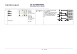
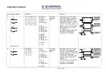
3
eSwitch_2o
Ö1
Ö2
A
0
0
0
1
0
0
0
1
0
1
1
1
LD E.1
AND E.2
ST IE.X
AND operation of both inputs
Öffner 2
Ausgang
Öffner 1
4
t
eSwitch_2oT
Ö1
Ö2
A
0
0
0
1
0
0
0
1
0
1
1
1
LD E.1
OR E.2
ST META_EN.1
LD E.1
AND E.2
ST METB_EN.1
LD MET.1
ST IE.X
Time monitoring
MET1..MET4
Like 3, but with time monitoring
of state changes.
In case of signal changes at S
or Ö a complementary signal
must follow within a period of
t=3 s. If not, detect fault and
A=0
Öffner 2
Ausgang
Öffner 1
max. 3 s
max. 3 s
Normally
closed
contact
Output
Normally
closed
contact
Normally
closed 2
Normally
closed 1
Normally
closed 2
Normally
closed 1
Output
Output
Output
max 3 s
max 3 s
Summary of Contents for PSCBR-C-10 Series
Page 1: ...Installation manual Page 1 of204 Installation Manual For PSCBR modules Series PSCBR C 10...
Page 178: ...Installation manual Page 178 of 204...
Page 181: ...Installation manual Page 181 of 204 Example for a risk analysis Gefahrenanalyse Risk analysis...


