Installation manual
Page 30 of204
Safety note:
The manufacturer's data (MTTFD, FIT-numbers, etc.) must be used for a safety related
assessment of the partial system "Sensors".
The DC-values listed in the table must be used conservatively and compliance with the
boundary conditions (see table under "Remarks") must be ensured.
According to the applicable standards, fault exclusions are permitted. The boundary
conditions mentioned in this context must permanently be met.
If several sensor systems are required for the correct function of a single safety
function, their partial values must be correctly merged by following the chosen method.
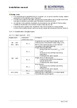
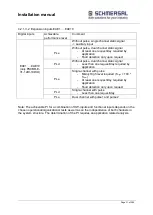
4.2.1.3 Classification of digital inputs
4.2.1.3.1 Basic inputs D1 ... D14
Digital inputs
Achievable
performance level
Comment
DI1 … DI4
DI9 … DI12
PL e
Suitable for any kind of input elements, with /
without pulse, achievable PI depending on the
MTTF
d
of the input element, as well as fault
exclusions in the external wiring.
DI5 … DI8
PL e
Single-channel with pulse:
-
Mainly High level required (T
High
> 100 *
T
Low
)
-
At least one request/day required by
application
-
Fault detection upon request
PL d
Single-channel without pulse:
-
Fault exclusion short-circuit between
signals and to VCC
-
Fault detection upon request
PL e
Dual channel:
-
At least one request/day required by
application
-
Fault detection upon request
DI13, DI14
PL e
Use of pulse1 and pulse2
Pl d
Without pulse / with pulse1 or 2 on both inputs
Fault detection upon request
Summary of Contents for PSCBR-C-10 Series
Page 1: ...Installation manual Page 1 of204 Installation Manual For PSCBR modules Series PSCBR C 10...
Page 178: ...Installation manual Page 178 of 204...
Page 181: ...Installation manual Page 181 of 204 Example for a risk analysis Gefahrenanalyse Risk analysis...


