Installation manual
Page 48 of204
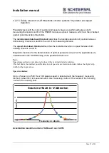
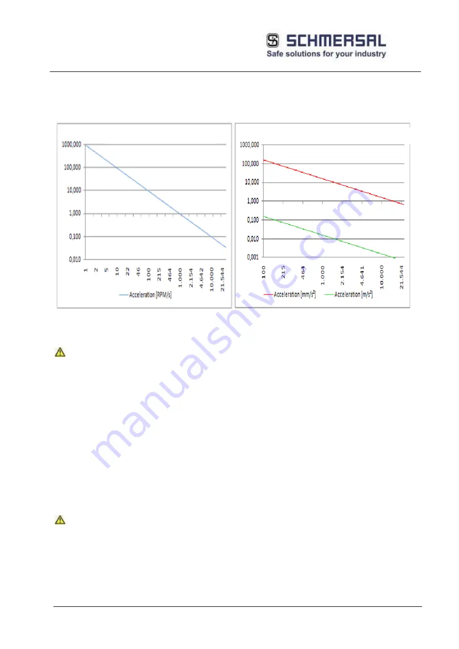
The digital acceleration resolution is limited by a maximum peak time of 256 ms and the encoder
resolution. The graphs below show the lowest measurable acceleration in dependence on the resolution in
revolutions/min, mm/s² and m/s².
Graph acceleration, rotary
Graph acceleration, linear
(Values in rev/min/s)
(Values in mm/s and m/s²)
Safety note:
The fault can be optimized by choosing a suitable sensor resolution for the corresponding
application.
For applications with limited resolution and/or time variance of the sensing signal, the
functional performance of the monitoring function used can be improved by using an
average filter. The average filter "smoothes" digital spurious components of the sensors.
However, this is achieved at the cost of a longer response time of the overall system.
The filter time can be variably set between 0 and 64 in steps of 8. The dimension is
"msec". In order to determine the response time of the overall system, the filter times must
be added to the specified response times of the PSCBR systems (see chapter 11).
Safety note:
The manufacturer's data (MTTF
D
, FIT-numbers, etc.) must be used for a safety related
assessment of the partial system "Sensors".
If the manufacturer demands specific diagnoses to be able to guarantee the specified
safety related characteristic values, these must be checked with respect to the specific
encoder as specified in the table "Specific diagnostic measures for position and speed
sensors". If in doubt, the matter must be clarified by the manufacturer.
Resolution
Resolution
Value
Value
Acceleration [rev/min/s]
Acceleration [mm/s
²
] and [m/s
²
]
Summary of Contents for PSCBR-C-10 Series
Page 1: ...Installation manual Page 1 of204 Installation Manual For PSCBR modules Series PSCBR C 10...
Page 178: ...Installation manual Page 178 of 204...
Page 181: ...Installation manual Page 181 of 204 Example for a risk analysis Gefahrenanalyse Risk analysis...


