Installation manual
Page 58 of204
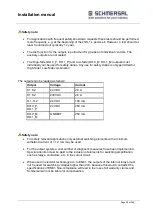
Safety note:
For applications with frequent safety shut-down requests these tests should be performed
more frequently, e.g. at the beginning of the shift, 1 x per week. However, a test should at
least be carried out cyclically 1 x year.
The test function for the outputs is performed for groups and individual controls. The
auxiliary outputs are not tested.
The High-Side (DO.0_P, DO.1_P) and Low-Side (DO.0_M, DO.1_M) outputs must
individually not be used for safety duties. Any use for safety duties is only permitted for
High-Side / Low-Side combination
The outputs can be loaded as follows:
Output
Voltage
Current
K1, K2
24 VDC
2.0 A
K1, K2
230VAC
2.0 A
O.1, O.2
24 VDC
100 mA
DO.0_P,
DO.1_P
24 VDC
250 mA
DO.0_M,
DO.1_M
GNDEXT
250 mA
Safety note:
For safety relevant applications only external switching elements with a minimum
withstand current of > 1.2 mA may be used.
For the output system a vast number of diagnostic measures have been implemented.
Special attention must be paid to the inclusion of elements for switching amplification,
such as relays, contactors, etc. in the cutout circuit.
When used in elevator technology acc. to EN81, the outputs of the internal relays must
not be used for switching voltages higher than 24V, because this would contradict the
specifications of EN81. Non-compliance will lead to the loss of all warranty claims and
Schmersal will not be liable for compensation.
Summary of Contents for PSCBR-C-10 Series
Page 1: ...Installation manual Page 1 of204 Installation Manual For PSCBR modules Series PSCBR C 10...
Page 178: ...Installation manual Page 178 of 204...
Page 181: ...Installation manual Page 181 of 204 Example for a risk analysis Gefahrenanalyse Risk analysis...


