Installation manual
Page 86 of204
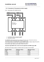
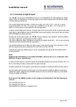
5.8 Connection of the external encoder supply
5.8.1 Incremental, HTL, SIN/COS, SSI
1)
SMX
Spannungs-
überwachung
der externen
Geber-
versorgungs-
spannungen
X
1
5
1
2
L+_ENC1
L-_ENC1
X
3
1
L
+
_
E
N
C
1
L
-_
E
N
C
1
9
2
L+_ENC1-2
L-_ENC1-2
X
3
3
L
+
_
E
N
C
2
L
-_
E
N
C
2
9
2
L+_ENC2
L-_ENC2
X
3
2
L
+
_
E
N
C
2
L
-_
E
N
C
2
9
2
L+_ENC2-2
L-_ENC2-2
X
3
4
L
+
_
E
N
C
2
L
-_
E
N
C
2
9
2
X
1
3
1
2
X
1
7
1
2
X
1
5
1
2
X
1
9
1
2
1)
1)
2)
2)
3)
3)
1)
Only PSCBR-C-10-SDM1-2 and PSCBR-C-10-SDM2-2
2)
Only PSCBR-C-10-SDM2 and PSCBR-C-10-SDM2-2
3)
Only PSCBR-C-10-SDM2-2
The PSCBR module supports encoder voltages of 5V, 8V, 10 V, 12V and 24V, which are
internally monitored in accordance with the chosen configuration.
If an encoder system is not supplied through the PSCBR module, a supply voltage still needs to
be connected to terminal X13 or X15 and configured accordingly.
The encoder supply must be protected with a fuse of max. 2A.
Important: Signal GND of the encoder must be equipotent to PSCBR supply GND
Monitoring of the supply voltage in accordance with the chosen nominal voltage:
Nominal voltage
Minimum voltage
Maximum voltage
5 VDC
4.4 VDC
5.6 VDC
8 VDC
7 VDC
9 VDC
10 VDC
8 VDC
12 VDC
12 VDC
10 VDC
14 VDC
24 VDC
20 VDC
29 VDC
Monitoring of
external encoder
supply voltages
Summary of Contents for PSCBR-C-10 Series
Page 1: ...Installation manual Page 1 of204 Installation Manual For PSCBR modules Series PSCBR C 10...
Page 178: ...Installation manual Page 178 of 204...
Page 181: ...Installation manual Page 181 of 204 Example for a risk analysis Gefahrenanalyse Risk analysis...


