Installation manual
Page 88 of204
5.9 Connection of digital inputs
The PSCBR comes with 14 (PSCBR-C-10/11/12) or 12 (PSCBR-E-31-12DI-10DIO) safe digital
inputs. These are suitable for connecting single or two-channel signals with and without cycling,
or without cross-shorting test.
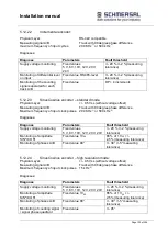
The connected signals must have a "High"-level of DC 24 V (DC +15 V...+ DC 30 V ) and a
"Low"-level of (DC -3 V...DC +5 V, type 1 acc. to EN61131-2). 24 VDC; +5 V, Type1 acc. to
EN61131-2 The inputs are provided with internal input filters.
A device internal diagnostic function cyclically tests the correct function of the inputs including the
input filters. A detected fault will set the PSCBR into an alarm status. At the same time all outputs
of the PSCBR are rendered passive.
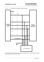
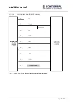
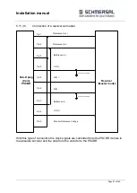
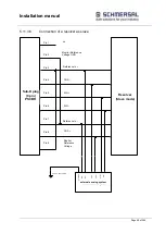
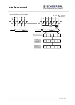
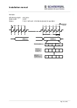
Besides the actual signal inputs, the PSCBR module holds two clock inputs P1 and P2 available.
The clock outputs are switching-type 24 VDC outputs.
The clock outputs are solely intended for monitoring the digital inputs (DI1 ... DI14) and cannot be
used for any other function within the application.
The switching frequency is 125 Hz for each output. In the planning stage one must bear in mind
that the outputs may only be loaded with a total current of max. 250 mA.
Furthermore, approved OSSD-outputs can be connected to the inputs DI1-DI4 and DI9-DI14
without limitation
Note:
Digital inputs DI5 to DI8 are not suitable for OSSDs, because there is no compliance with
EN 61131-2 Type 2 requirements.
In case of single-channel use of the inputs, the achievable safety level must be limited to SIL 2 or
PL d, if the safety function is demanded at regular intervals.
A safety related use of the inputs is generally only intended in connection with the pulse outputs.
If pulse outputs are not used, short circuits in the external wiring between different inputs and
against the supply voltage for the PSCBR must be ruled out by external measures, appropriate
routing of cables in particular.
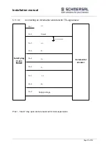
Each input of the PSCBR module can be configured individually for the following signal
sources:
Input assigned to pulse P1
Input assigned to pulse P2
Input assigned to continuous voltage DC 24 V
Summary of Contents for PSCBR-C-10 Series
Page 1: ...Installation manual Page 1 of204 Installation Manual For PSCBR modules Series PSCBR C 10...
Page 178: ...Installation manual Page 178 of 204...
Page 181: ...Installation manual Page 181 of 204 Example for a risk analysis Gefahrenanalyse Risk analysis...

