Installation manual
Page 90 of204
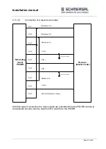
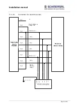
5.11 Connection of position and speed sensors
5.11.1 General notes
Depending on module type the PSCBR module (PSCBR-C-10-SDM1/PSCBR-C-10-SDM2) has
(1/2) external encoder interfaces for the connection of industrial incremental and absolute
encoders. The encoder interfaces can be configured as incremental, SIN/COS, or as absolute
SSI-encoders.
It is also possible to connect 2 incremental signal generating sensors (e.g. proximity switches)
to the counting inputs of the PSCBR module. The signals must each be read in with normal and
complementary track.
IMPORTANT
The voltage supply of the encoder system uses the dedicated terminals on the PSCBR module.
This voltage is applied to the encoder plug and monitored by an internal diagnostic process.
When the sensor is supplied with an external voltage, this voltage must be supplied through the
encoder plug. The corresponding terminal (encoder supply voltage) on the PSCBR module
remains unoccupied.
If an external sensor voltage supply is not recirculated through the encoder plug, any failure of
this supply must be included in the fault examination of the overall system. This, in particular,
requires evidence that this fault is detected or can be excluded when the specified operating
voltage of the overall system is fallen short of / exceeded.
EMC - measures such as shielding etc. must be observed.
The two encoders must be non-interacting to each other. This applies for both the electrical as
well as the mechanical part.
If both encoders are coupled to the facility to be monitored via common mechanical parts, the
connection must be positively designed and should not have any parts that are susceptible to
wear (chains, toothed belts, etc.). Should this be the case, additional monitoring features for the
mechanical connection of the sensors (e.g. monitoring of a toothed belt) are required).
In case of an active position processing at least one absolute value encoder must be used.
When using two equivalent sensors one must make sure that the sensor with the higher
resolution is configured as sensor 1 (process sensor) and the sensor with the lower resolution
as sensor 2 (reference sensor).
Important: Signal GND of the encoder must be equipotent to PSCBR supply GND. This
applies although on Resolver-type encoders.
Summary of Contents for PSCBR-C-10 Series
Page 1: ...Installation manual Page 1 of204 Installation Manual For PSCBR modules Series PSCBR C 10...
Page 178: ...Installation manual Page 178 of 204...
Page 181: ...Installation manual Page 181 of 204 Example for a risk analysis Gefahrenanalyse Risk analysis...

