Installation manual
Page 105 of204
5.12.2.6
Extended monitoring proximity switch / proximity switch
The extended monitoring uncovers the following faults:
a) Supply voltage failure
b) Failure of output signal in driver direction
c) Malfunction of High signal proximity switch
d) Interruption of signal path
e) Mechanical de-adjustment of proximity switch / excessive switching distance of proximity
switch
For diagnostic purposes both status conditions of the counting signal are additionally recorded
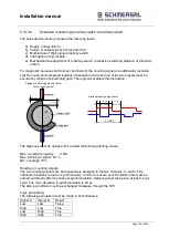
synchronously and compared logically. Attenuation of at least one of the two signals must be
ensured by means of a switching gate. The logic will evaluate this instruction.
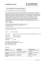
The diagnose must be designed for at least the following limiting values:
Max. counting frequency:
4 kHz
Max. blanking 0-signal: 50 %
Min. coverage 10 %
Reading in counting signals:
The two counting signals are both separately assigned to the two channels. In each of the
channels the status is read in synchronously. In order to ensure synchronization this must be
carried out directly after the channel synchronization. Sampling must take place at least 1x per
cycle. The max. deviation in synchronization is 20 µs.
The status conditions must be exchanged crosswise through the SPI.
Logic processing:
The following evaluation must be made in both channels:
Signal A
Signal B
Result
Low
Low
False
High
Low
True
Low
High
True
High
High
True
120°
Sensor A
Sensor B
min 3mm
max 0.5mm
T=100%
33.3%
16.7
33.3%
16.7
Intended theoretic signal form
Design of switching gate with radial
sensor arrangement
Spindle shaft
Switching gate
Summary of Contents for PSCBR-C-10 Series
Page 1: ...Installation manual Page 1 of204 Installation Manual For PSCBR modules Series PSCBR C 10...
Page 178: ...Installation manual Page 178 of 204...
Page 181: ...Installation manual Page 181 of 204 Example for a risk analysis Gefahrenanalyse Risk analysis...

