Installation manual
Page 113 of204
7 Start-up
7.1 Procedure
Start-up must only be performed by qualified personnel!
Strictly follow the safety regulations when commissioning!
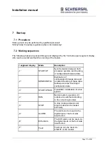
7.2 Making sequences
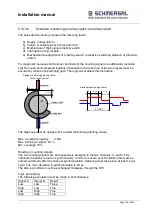
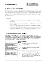
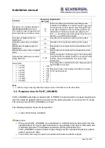
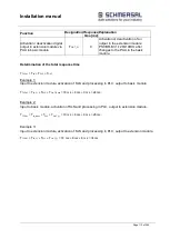
The following phases are passed through and displayed by the front side seven segment display
after each new start and fault-free running of the module:
7 segment display
Mode
Description
„1“
STARTUP
Synchronization between both
processor systems and checking
of configuration/firmware data
„2“
SENDCONFIG
Distribution of
configuration/firmware data and
renewed checking of these data.
Subsequent area checking of
configuration data.
„3“
STARTUP BUS
If available, initialization of a bus
system
„4“
RUN
Normal system operation. All
outputs are switched according
to the current logic status.
„5“
STOP
In stop mode parameter and
program data can be loaded
externally.
„A“
ALARM
The alarm can be reset via the
digital input or the front side
reset button.
„E“
ECS-Alarm
The ECS alarm can be reset via
the digital inputs or the front side
reset button.
„F“
Fault
Fault can only be reset via
ON/OFF of the module.
Summary of Contents for PSCBR-C-10 Series
Page 1: ...Installation manual Page 1 of204 Installation Manual For PSCBR modules Series PSCBR C 10...
Page 178: ...Installation manual Page 178 of 204...
Page 181: ...Installation manual Page 181 of 204 Example for a risk analysis Gefahrenanalyse Risk analysis...


