Installation manual
Page 26 of204
4.2 Safety related characteristic data and wiring for the connected
sensors
The PSCBR modules have completely separated signal processing paths for each safety
input. This applies for both the digital and the analog inputs. Furthermore, measures for
achieving the highest possible DC-values have been implemented.
4.2.1 Digital sensors:
Digital inputs and outputs are generally of a completely redundant design, except the electro-
magnetic input terminal. The following list contains details for classification, the DC and the
achievable PI or SIL.
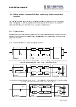
4.2.1.1 Characteristics of sensors / input elements
I
A
O
A
L
A
I
B
O
B
L
B
m
m
i
i
c
i
m
i
m
Sensor
PES
Aktuator
S
A
S
B
Two-channel input element in parallel connection (Cat. fault tolerance 1) with high DC caused by signal processing
in two channels and diagnose by means of cross-comparison in the PES
I
A
O
A
L
A
I
B
O
B
L
B
m
m
i
i
c
i
m
i
m
Sensor
PES
Aktuator
S
A
=K1
K1
K2
S
B
=K2
Two-channel input element in series connection (Cat. 4, fault tolerance 1) with low to medium DC caused by signal
processing in two channels and diagnose by means of cyclic testing
I
A
O
A
L
A
I
B
O
B
L
B
m
m
i
i
c
i
m
i
m
Sensor
PES
Aktuator
K1
K2
S1
Actuator
Sensor
PES
Sensor
Actuator
PES
Sensor
Actuator
PES
Summary of Contents for PSCBR-C-10 Series
Page 1: ...Installation manual Page 1 of204 Installation Manual For PSCBR modules Series PSCBR C 10...
Page 178: ...Installation manual Page 178 of 204...
Page 181: ...Installation manual Page 181 of 204 Example for a risk analysis Gefahrenanalyse Risk analysis...


