Installation manual
Page 53 of204
Safety note:
The manufacturer's data (MTTF
D
, FIT-numbers, etc.) must be used for a safety related
assessment of the partial system "Sensors".
The DC-values listed in the table must be used conservatively and compliance with the
boundary conditions (see table under "Remarks") must be ensured.
According to the applicable standards, fault exclusions are permitted. The boundary
conditions mentioned in this context must permanently be met.
If several sensor systems are required for the correct function of a single safety function,
their partial values must be correctly merged by following the chosen method. This applies
also for a combination of digital and analog sensors (e.g. safely reduced speed with open
safety door = door c encoder for speed detection)
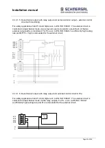
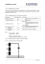
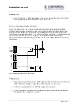
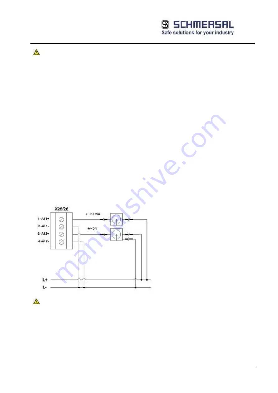
4.2.3.1 Exemplary connection of analog sensors
By using suitable sensors and careful wiring of the sensor
OI e acc. to EN ISO 13849 can be achieved.
The analog current inputs are all equipped with the fixed loading resistor of 500Ohm. For analog
voltage inputs this resistor is omitted.
Safety note:
PI e acc. to EN ISO 134849-1 is achieved when using two non-reactive sensors, for which
Common Cause faults can be ruled out.
Summary of Contents for PSCBR-C-10 Series
Page 1: ...Installation manual Page 1 of204 Installation Manual For PSCBR modules Series PSCBR C 10...
Page 178: ...Installation manual Page 178 of 204...
Page 181: ...Installation manual Page 181 of 204 Example for a risk analysis Gefahrenanalyse Risk analysis...


