Installation manual
Page 57 of204
4.3.3 Basic outputs
The modules
PSCBR-C-10, PSCBR-C-10-SDM1, PSCBR-C-10-SDM1-1, PSCBR-C-10-SDM2,
PSCBR-C-10-SDM2-
PSCBR-E-31-12DI-10DIO
all have basic outputs of identical design.
The PSCBR module provides a total of 8 outputs, which can be interconnected individually or in
groups.
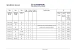
Output
Architecture acc. to
EN ISO 13849-1
Comment
K1 and K2
4
Complete tripping channel in compliance
with architecture category 4 acc. to EN
ISO 13849-1
K1
Not safe
Only functional
K2
Not safe
Only functional
DO0_P and
DO0_M
4
Complete tripping channel in compliance
with architecture category 4 acc. to
EN ISO 13849-1
DO0_P
Not safe
Only functional
DO0_M
Not safe
Only functional
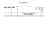
DO1_P and
DO1_M
4
Complete tripping channel in compliance
with architecture category 4 acc. to
EN ISO 13849-1
DO1_P
Not safe
Only functional
DO1_M
Not safe
Only functional
O.1
Not safe
Signalling/auxiliary output
O.2
Not safe
Signalling/auxiliary output
The HISIDE and LOWSIDE outputs are subjected to a plausibility test in all operating states. In
switched on state the correct function of all outputs is tested with a cyclic test pulse. For this
purpose the output is switched to the corresponding inverse value for a test period TT <300µs,
i.e. one P-output is switched instantaneously to 0 VDC potential, while one M-output is switched
to 24 VDC potential.
ay outputs a onito o p ausi i ity u in a swit in y The relay outputs
must be switched cyclically and thus tested to maintain the safety function. The switching/test
cycle is determined in dependence on the application.
Summary of Contents for PSCBR-C-10 Series
Page 1: ...Installation manual Page 1 of204 Installation Manual For PSCBR modules Series PSCBR C 10...
Page 178: ...Installation manual Page 178 of 204...
Page 181: ...Installation manual Page 181 of 204 Example for a risk analysis Gefahrenanalyse Risk analysis...

