Installation manual
Page 76 of204
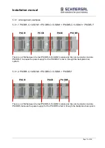
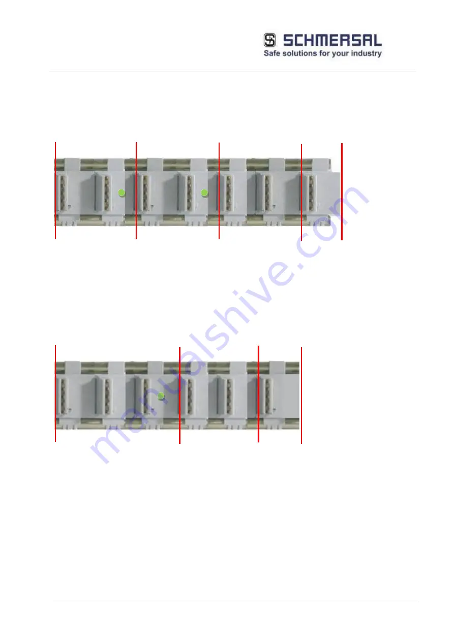
5.3.1 Arrangement examples
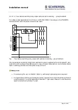
5.3.1.1 PSCBR-C-10-SDM1 + PSCBR-C-10-SDM1 + PSCBR-C-10-SDM1 + PSCBR-F
There is no TB2 between the last PSCBR-C-10-SDM1 module and the communication module
PSCBR-F, because the power supply for the PSCBR-F is fed in through the backplane bus
system.
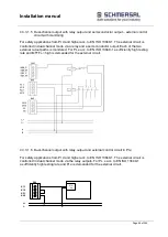
5.3.1.2 PSCBR-C-10-SDM2 + PSCBR-C-10-SDM1 + PSCBR-F
There is no TB2 between the last PSCBR-C-10-SDM1 module and the communication module
PSCBR5, because the power supply for the PSCBR5 is fed in through the backplane bus system.
PSCBR
-F
PSCB
R-C-
PSCB
R-C-
PSCB
R-C-
PSCB
R-C-
PSCB
R-C-
PSCBR
-F
Summary of Contents for PSCBR-C-10 Series
Page 1: ...Installation manual Page 1 of204 Installation Manual For PSCBR modules Series PSCBR C 10...
Page 178: ...Installation manual Page 178 of 204...
Page 181: ...Installation manual Page 181 of 204 Example for a risk analysis Gefahrenanalyse Risk analysis...

