2
Operating instructions
Safety fieldbox
SFB-PN-IRT-8M12-IOP-V2
EN
1.6 General safety instructions
The user must observe the safety instructions in this operating
instructions manual, the country specific installation standards as well
as all prevailing safety regulations and accident prevention rules.
The information contained in this operating instructions manual is
provided without liability and is subject to technical modifications. There
are no residual risks, provided that the safety instructions as well as
the instructions regarding mounting, commissioning, operation and
maintenance are observed.
1.7 Warning about misuse
In the event of improper or unintended use or tampering,
use of the safety fieldbox could expose persons to danger
or cause damage to the machine or system components.
1.8 Exclusion of liability
We shall accept no liability for damages and malfunctions resulting from
defective mounting or failure to comply with this operating instructions
manual. The manufacturer shall accept no liability for damages
resulting from the use of unauthorised spare parts or accessories.
For safety reasons, invasive work on the device as well as arbitrary
repairs, conversions and modifications to the device are strictly
forbidden; the manufacturer shall accept no liability for damages
resulting from such invasive work, arbitrary repairs, conversions and/or
modifications to the device.
2. Product description
2.1 Ordering code
This operating instructions manual applies to the following types:
SFB-PN-IRT-8M12-IOP-V2
Option
Description
SFB
Safety fieldbox
PN
PROFINET
IRT
Switch IRT-capable
8M12
8 device ports for M12 connector, 8-pole
IOP
Device connection: IO parallel
V2
Version 2
2.2 Purpose
The SFB-PN-IRT-8M12-IOP-V2 safety fieldbox is designed for
connection of up to 8 safety switchgear units with parallel IO signals to
a PROFINET/PROFIsafe network.
A maximum of 4 BDF200-FB control panels can be connected.
Only safety switchgears are allowed to be connected for
which the feedback of an external voltage can be safely
excluded.
The safety signals from the connected safety switchgear are forwarded
to a safety controller via the safety field bus for evaluation.
For larger safety applications, multiple fieldboxes can be connected to
the power supply and field bus in series.
The user must evaluate and design the safety chain in
accordance with the relevant standards and the required
safety level.
The non-safe IO signals of the connected devices are connected to the
control system via the field bus.
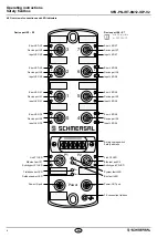
Safety switchgear with parallel IO signals can be connected to
device ports X0 - X7.
BDF200-FB control panels can only be connected to
device ports X4 - X7.
Manual: Safety fieldbox SFB-PN-V2
Further information on the commissioning of the safety
SFB-PN-V2 fieldbox can be found in the manual.
GSDML file for safety fieldbox SFB-PN-V2
The dual-language GSDML file for the SFB-PN-V2 can be found
on the internet at
products.schmersal.com
after searching
'SFB-PN'.
A GSDML file is also saved in the device. The file can be
downloaded via the integrated web server (see 'Info' page).
2.3 Technical data
Standards:
EN 61131-1, EN 61131-2, EN 60947-5-3
EN ISO 13849-1, IEC 61508
Time to readiness:
≤ 8 s
Worst Case Delay Time Input acc. DIN EN 61784-3-3:
≤ 20 ms
Worst Case Delay Time Output acc. DIN EN 61784-3-3:
≤ 50 ms
Device Watchdog Time acc. DIN EN 61784-3-3:
10 ms
Device Acknowledgement Time acc. DIN EN 61784-3-3:
≤ 25 ms
Materials:
- Enclosure:
polyamide / PA 6 GF
- Viewing window:
polyamide / PACM 12
- Encapsulation:
polyurethane / 2K PU
- Labelling plates:
polyamide / PA
Mechanical data
Electrical connection version:
Built-in socket / connector
-
Device ports X0 - X7:
M12/8-pole, A-coded
- Power I/O:
M12-POWER/4-pole, T-coded
- PROFINET P1/P2:
M12/4-pole, D-coded
M12 connector tightening torque:
min. 0.8 Nm / max. 1.5 Nm
- Recommended for Schmersal cables:
1.0 Nm
Fixing screws:
2 x M6
- Tightening torque:
max. 3.0 Nm
Viewing window screws:
2 x Torx 10
- Tightening torque:
0.5 … 0.6
Nm
Ambient conditions
Ambient temperature:
−25 °C … +55 °C
Storage and transport temperature:
−25 °C … +70 °C
Relative humidity:
10 % … 95 %, non condensing
Resistance to shock:
30 g / 11 ms
Resistance to vibration:
5 … 10 Hz, amplitude 3.5 mm;
10 … 150 Hz, amplitude 0.35 mm / 5 g
Degree of protection:
IP66/IP67 acc. EN 60529
Installation altitude above sea level:
max. 2,000 m
Protection class:
III
Insulation values to EN 60664-1:
- Rated insulation voltage U
i
:
32 VDC
- Rated impulse withstand voltage U
imp
:
0.8 kV
- Over-voltage category:
III
- Degree of pollution:
3
Electrical data – Power I/O
Supply voltage U
B
:
24 VDC -15% / +10%
(stabilised PELV mains unit)
Current consumption SFB:
200 mA
Rated operating voltage U
e
:
24 VDC
Rated operating current I
e
:
10 A
(external fuse protection required)
Device fuse rating:
≤ 10 A slow blow when used to UL 61010
Adapters providing field wiring means are available from
the manufacturer. Refer to manufacurer's information.
Use power cables with minimum AWG14, 80°C, 24Vdc rating.
UL 248 fuse (slow blow) or UL 489 Circuit breaker,
rated max. 10 A or equivalent.


