5
SFB-PN-IRT-8M12-IOP-V2
Operating instructions
Safety fieldbox
EN
4. Electrical connection
4.1 General information for electrical connection
The electrical connection may only be carried out by
authorised personnel in a de-energised condition.
To supply the safety fieldbox, M12 power connectors, cables with a
cross-section of max. 1.5 mm² can be connected to the fieldbox.
In case of a fault, a voltage of up to 60 V can be applied to
the device ports.
4.2 Notes for replacing the device
To replace a defective SFB, follow the steps below:
- Bring the machine and the SFB into a de-energised state
- Check replacement device for correct version
This product must only be replaced in the application by an
identical product of type SFB-PN-IRT-8M12-IOP-V2 with
part no. 103040357.
The older product version has a lower safety level.
The replacement of the older SFB-PN-IRT-8M12-IOP with
the newer SFB-PN-IRT-8M12-IOP-V2 is possible.
- The replacement device must be in the delivery state.
If necessary, carry out a "factory reset" (see 4.10).
- Set or transfer the safety address to the new device (see 4.10).
- Mount and install the unit
- Put the system and SFB back into operation
- Check all safety functions
The simple device change is only possible if the
"Support device replacement without exchangeable medium"
has been activated in the F-CPU for the PROFINET
interface under
"General / Advanced options / Interface options".
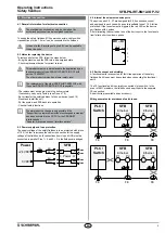
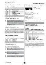
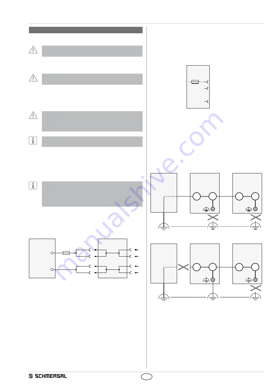
4.3 Power supply and fuse protection
The supply voltage of the safety fieldbox is to be protected with a fuse
of 10 A. In order to increase the cable cross section for the supply
voltage of the fieldbox, both connections from Us and GND must be
connected in parallel. Pins 1 + 4 and 2 + 3 in the fieldbox are bridged.
0 VDC
+24 VDC
Power
10A
BN
1
BK
4
3
2
BU
WH
SFB
1
4
3
2
I Power O
GND
GND
Us
Us
4.4 Internal fuse elements device ports
The device ports X0 - X7 are designed for 0.8 A continuous current
and equipped in each case with an auto-resettable fuse of 1.5 A for line
protection. If the fuse element is triggered, the red LED on the device
port flashes with 4 pulses.
After eliminating the overload at one of the device ports, the fuse resets
itself after a short cool-down phase.
X0 – X7
1
2
A1
1,5A
8
...
4.5 Earth concept and shielding
A functional earth is connected for fault-free operation of the safety
fieldbox. Earth loops must be avoided when connecting the functional
earth.
The FE functional earth is normally connected via the switch. In the
event of EMC problems, the fieldbox can be earthed via the separate
FE connection.
An earth strap is available as an accessory.
Wiring examples for avoidance of earth loops:
FE
SFB
P1
P2
Ethernet
FE
SPS /
Switch
FE
SFB
P1
P2
Ethernet
PLC /
FE
SFB
P1
P2
Ethernet
FE
SPS /
Switch
FE
SFB
P1
P2
Ethernet
PLC /


