9
SFB-PN-IRT-8M12-IOP-V2
Operating instructions
Safety fieldbox
EN
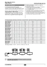
8. Annex system configuration
8.1 Configuration examples of the power supply
If the power supply of each fieldbox is separated and in a star
configuration, the maximum cable length of a fieldbox series is limited
only by the maximum permissible cable length of the field bus used.
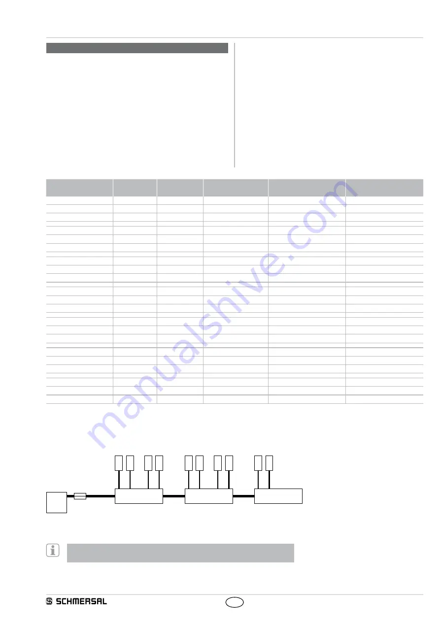
If the power supply from fieldbox to fieldbox is looped through,
the following maximum configurations apply.
3 different configurations are shown respectively for the different
SCHMERSAL safety switchgear. One configuration with long cable
lengths (maximum), one configuration with medium cable lengths
(medium) and one configuration with shorter cable lengths (small).
The following assumptions are made for the configuration
examples listed in the table:
• The examples represent maximum configurations. If individual cable
lengths are shortened, larger systems are possible.
• 2 x 1.5 mm² power supply wiring and 10 A fuse protection.
• Use of SCHMERSAL cables.
• The cable lengths listed in the table between the power supply and
the first fieldbox as well as the individual fieldboxes are the maximum
lengths. Reducing the individual cable lengths is not critical.
• For interlocks, these designs are based on simultaneous activation of
all lock and unlock functions. In the event of delayed activation of the
lock and unlock function, larger systems are possible.
Device / configuration
version
Max. number
of devices
Equals number
of fieldboxes
Length of the cable (A)
up to the first fieldbox
Length of the cables (B)
between the fieldboxes
Length of stub cables (C)
for device connection
AZM 201 / Maximum
16
2
10.0 m
10.0 m
7.5 m
AZM 201 / Medium
20
2.5
7.5 m
7.5 m
5.0 m
AZM 201 / Small
24
3
7.5 m
5 m
3.5 m
MZM 100 / Maximum
20
2.5
10.0 m
10.0 m
7.5 m
MZM 100 / Medium
24
3
7.5 m
7.5 m
5.0 m
MZM 100 / Small
28
3.5
7.5 m
5 m
3.5 m
AZM 300 / Maximum
28
3.5
10.0 m
10.0 m
7.5 m
AZM 300 / Medium
32
4
7.5 m
7.5 m
5.0 m
AZM 300 / Small
40
5
7.5 m
5 m
3.5 m
AZM 400 / Maximum
16
2
10.0 m
10.0 m
7.5 m
AZM 400 / Medium
16
2
7.5 m
7.5 m
5.0 m
AZM 400 / Small
16
2
7.5 m
5 m
3.5 m
AZM 1xx / Maximum
20
2.5
10.0 m
10.0 m
7.5 m
AZM 1xx / Medium
24
3
7.5 m
7.5 m
5.0 m
AZM 1xx / Small
28
3.5
7.5 m
5 m
3.5 m
RSS & CSS / Maximum
48
6
10.0 m
10.0 m
7.5 m
RSS & CSS / Medium
56
7
7.5 m
7.5 m
5.0 m
RSS & CSS / Small
64
8
7.5 m
5 m
3.5 m
Mixed / Maximum
24
3
10.0 m
10.0 m
7.5 m
Mixed / Medium
28
3.5
7.5 m
7.5 m
5.0 m
Mixed / Small
32
4
7.5 m
5 m
3.5 m
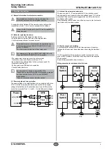
Mixed fitting of fieldbox:
2 x AZM 201, 2 x MZM 100, 2 x AZM 300 and 2 x RSS / CSS
Power
(A)
(B)
(B)
(C)
24 VDC
1
2
(C)
...
1
2
7
8
(C)
...
1
2
7
8
Fuse
10 A
Power supply
Fieldbox
Fieldbox
Fieldbox
Devices
Devices
Devices
Fuse
A useful design tool for calculating the real voltage drops is available on the Internet at
www.system-engineering-tool.com


