7
SFB-PN-IRT-8M12-IOP
Operating instructions
Safety fieldbox
EN
4.6 Connector configuration of device ports X0 – X7
Version: M12 socket, 8-pin, A-coded
PIN Colour* Signal Description of fieldbox signals
1
WH
A1
+ 24 VDC device supply
2
BN
Y1
Test pulse output 1,
safety channel 1 supply
3
GN
A2
0 VDC device supply
4
YE
X1
Safety input 1
5
GY
DI
Diagnostic input
6
PK
Y2
Test pulse output 2,
safety channel 2 supply
7
BU
X2
Safety input 2
8
RD
DO
Safe output
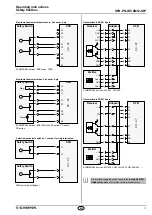
X4 – X7 additional with FB interface for BDF200-FB
The default setting is used for safety switchgear with
electronic OSSDs. If safety switchgear with dry contacts are
used, cross fault monitoring must be activated.
For safety switchgear with electronic OSSDs, cross fault
detection of the device connection cable must be carried
out by the safety switchgear.
4.7 Connector configuration POWER I/O
Version: M12 power connector/socket, 4-pin, T-coded
PIN Colour* Signal Description of fieldbox signals
1
BN
Us
+ 24 VDC SFB supply
(= PIN 4)
2
WH
GND
0 VDC SFB supply
(= PIN 3)
3
BU
GND
0 VDC SFB supply
(= PIN 2)
4
BK
Us
+ 24 VDC SFB supply
(= PIN 1)
4.8 Connector configuration PROFINET P1/P2
Version: M12 socket, 4-pin, D-coded
PIN Colour* Signal Description of fieldbox signals
1
YE
TD+
Transmit-Data +
2
WH
RD+
Receive-Data +
3
OG
TD-
Transmit-Data -
4
BU
RD-
Receive-Data -
Flange
FE
Ethernet shielding
* Colour code of SCHMERSAL M12 cables
4.9 Setting the F-address and factory reset
Carefully remove the viewing window. (Screws Torx 10)
The screws in the viewing window are not secured.
Keep the screws safe so that they do not get lost.
Caution!
Electrostatically sensitive components.
Do not touch the printed circuit board directly.
When you open the inspection window, ensure that no
moisture or excessive humidity penetrates into the fieldbox.
The 3 rotary coding switches behind the viewing window can be used to
set the safety address and to carry out a factory reset of the SFB.
0 1
2
3
4
5
6
7
8
9
0 1
2
3
4
5
6
7
8
9
0 1
2
3
4
5
6
7
8
9
x 100
x 10
x 1
F address
1 - 999
Valid F address
0 - 0 - 0
Factory reset
Setting of the F address
• Remove power from the SFB
• Set the desired F address in the range 1 - 999
• Resupply power to the SFB
Carrying out an SFB factory reset:
• Remove power from the SFB
• Setting of F address 0 – 0 – 0
• Resupply power to the SFB
• After 15 seconds, switch off the power of the SFB-PN again
The IP address and the PROFINET name are deleted during a factory
reset.
5. Diagnostic functions
5.1 LED indicators, device ports X0 - X7
There are 2 LED indicators on each device port.
A green/red error LED and a yellow input LED to display the switching
condition at the safety inputs.
Error LED (E)
The error LED may exhibit the following display and flashing pattern:
LED display
Description
GREEN
ON
No fault at device
port
GREEN
Flashes
Device port fault can be acknowledged
RED
1 impulse
Safety input cross-fault
RED
2 impulses Safety input fault
RED
3 impulses Test pulse output fault
RED
4 impulses Device supply overload
RED
5 impulses Digital output overload
RED
6 impulses Digital output fault
RED
7 impulses FB interface fault (only device ports 4-7)
Input LED (I)
The input LED may exhibit the following display and flashing pattern:
LED display
Description
YELLOW OFF
Both safety inputs LOW
YELLOW
ON
Both safety inputs HIGH
YELLOW Flashes
Only one safety input HIGH,
or discrepancy/stable time fault


