36
3 Installation
3.2.5
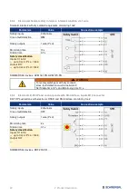
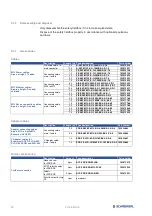
Connector device ports X0 – X7
Version: M12 socket, 8-pin, A-coded
Pin assignment
Pin Colour Signal
Description of fieldbox signals
1
WH
A1
+24 VDC device supply, internal fused, max. 0.8 A
2
BN
Y1
Test pulse output 1, supply safety channel 1
3
GN
A2
0 VDC device supply
4
YE
X1
Safety input 1
5
GY
DI
Diagnostic input
6
PK
Y2
Test pulse output 2, supply safety channel 2
7
BU
X2
Safety input 2
8
RD
DO
Safety output, max. 0.8 A
CAUTION
The pulse output / safety output Y1 can be loaded with a maximum of 15 mA at
24 VDC. The pulse output / safety output Y2 can be loaded with a maximum of
10 mA at 24 VDC and of 30 mA at 0 VDC.
3.2.6
Connector Power I/O
Version: M12-Power connector / socket, 4-pin, T-coded
Pin assignment
Pin Colour Signal
Description of fieldbox signals
1
BN
Us
+24 VDC power supply SFB (bridged with Pin 4)
2
WH
GND
0 VDC power supply SFB (bridged with Pin 3)
3
BU
GND
0 VDC power supply SFB (bridged with Pin 2)
4
BK
Us
+24 VDC power supply SFB (bridged with Pin 1)
3.2.7
Connector PROFINET P1/P2
Version: M12 socket, 4-pin, D-coded
Pin assignment
Pin Colour Signal
Description of fieldbox signals
1
YE
TD+
Transmit-Data +
2
WH
RD+
Receive-Data +
3
OG
TD-
Transmit-Data -
4
BU
RD-
Receive Data -
Flange
FE
Ethernet shielding
* Colour code of the SCHMERSAL M12 cables, acc. DIN 47100
M12, 4-pin
M12, 8-pin
Pin
Wire colour
Pin
Wire colour
1
BN
Brown
1
WH
White
2
WH
White
2
BN
Brown
3
BU
Blue
3
GN
Green
4
BK
Black
4
YE
Yellow
-
-
-
5
GY
Grey
-
-
-
6
PK
Pink
-
-
-
7
BU
Blue
-
-
-
8
RD
Red

