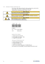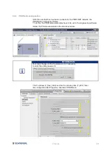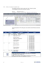
3 Installation
37
3.3 LED diagnostic indicators
3.3.1
LED indicators, device ports X0 – X7
There are 2 LED indicators on each device port.
A green/red error LED and a yellow input LED to display the switching condition
at the safety inputs.
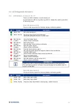
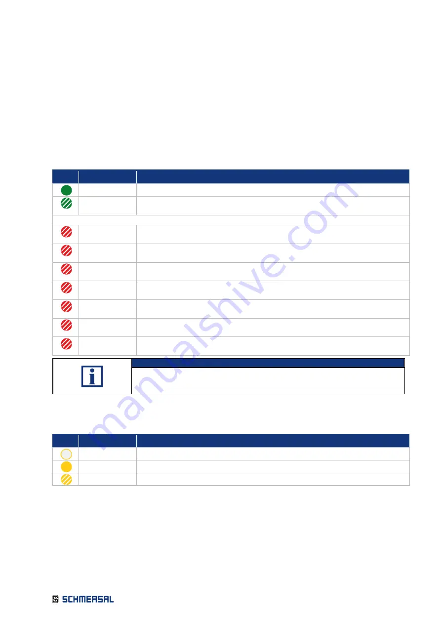
Error LED device ports (E)
The error LED may exhibit the following display and flashing pattern:
LED
Display
Description
Green, ON
No fault at device port
Green, flashes Device port fault can be acknowledged
Send acknowledgement pulse or power reset
Red, flashes
1 pulses
Cross-fault safety inputs
Check cord set and device
Red, flashes
2 pulses
Fault safety inputs
No test pulses, check cord set and device
Red, flashes
3 pulses
Fault test pulse outputs
Check cord set and device
Red, flashes
4 pulses
Overload device power supply
Fuse device power supply has tripped, check cord set and device
Red, flashes
5 pulses
Overload digital output
Current limiter activated, check cord set and device
Red, flashes
6 pulses
Cross-fault digital output
Check cord set and device
Red, flashes
7 pulses
Fault FB-Interface (only device port 4-7)
Check cord set and device
INFORMATION
Some errors can no longer be detected after passivation of the device port.
The red flashing patterns for these errors are displayed at the affected port for
approx. 60 seconds.
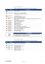
Input-LED device ports (I)
The input LED may exhibit the following display and flashing pattern:
LED
Display
Description
Yellow, OFF
Both safety inputs LOW
Yellow, ON
Both safety inputs HIGH
Yellow, flashes Only one safety input HIGH, or discrepancy / stable time error


