52
4 Set-up
4.3.6
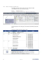
Address assignment and data areas
The address assignment and the data areas of the individual modules
of the SFB-PN can be found in the device overview.
Module:
SFB Module Data_1
Submodule: FS data / Functional data / Diagnosis and FB-Interface
The bit assignments of the data bytes of the individual submodules are described
below.
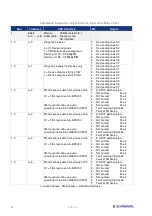
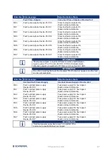
Submodule: FS data, Input data (SFB => PLC)
Slot
I-Address
SFB Data Byte
Bit
Signal
1
6 Byte
(n+0 … n+5)
Module:
SFB Module Data_1
Submodule: FS data
1 1
n+0
Safety Input X1/X2
2-channel device
Safety Inputs X1 AND X2
1-channel device
Safety Input X1
0
1
2
3
4
5
6
7
Device port X0
Device port X1
Device port X2
Device port X3
Device port X4
Device port X5
Device port X6
Device port X7
1 1
n+1
Safety Input X2
2-channel device
---
1-channel device
Safety Input X2
0
1
2
3
4
5
6
7
Device port X0
Device port X1
Device port X2
Device port X3
Device port X4
Device port X5
Device port X6
Device port X7
1 1
n+2 … n+5
Safety-Header
Internal FS data
n = base address
INFORMATION
If
one
2-channel device is connected, only
1
safety bit is transmitted
in PROFINET at the I-Address n+0
If
two
1-channel devices are connected,
2
safety bits are transmitted
separately for each device at I-Addresses n+0 and n+1.


