3
SLB 200
Operating instructions
Safety light barrier
EN
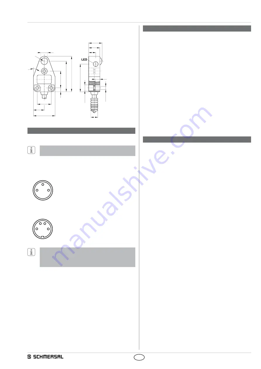
3.2 Dimensions
All measurements in mm.
9,6
R7
6,75
20°
18,8
30,8
39
,4
50
,3
4
3,
4
24
5,
5
15,5
20
16,1
10
ø
8,
5
(6
x)
ø4
,4
(3
x)
ø 10
4. Electrical connection
4.1 General information for electrical connection
The electrical connection may only be carried out by
authorised personnel in a de-energised condition.
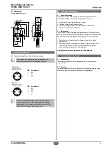
Transmitter
SLB 200-E31-21
4
3
1
PIN
Description
1
BN
3
n.c.
4
WH
Receiver
SLB 200-R31-21
3
1
4
2
PIN
Description
1
BN
2
WH
3
n.c.
4
n.c.
Further information about the wiring and connection of
the safety light barrier to the safety-monitoring module
can be found in the operating instructions manual of the
SLB 200-C04-1R safety-monitoring module.
5. Set-up and maintenance
5.1 Functional testing
The safety function of the safety components must be tested. The
following conditions must be previously checked and met:
1. Correct fixing of the transmitter and receiver.
2. Fitting and integrity of the power cable.
3. If one or more light barriers are interrupted, the hazardous
movement is brought to standstill.
5.2 Maintenance
In the case of correct installation and adequate use, the safety switch-
gear features maintenance-free functionality. A regular visual inspection
and functional test, including the following steps, is recommended:
1. Check the correct mounting of the fixing screws on the safety
light barriers.
2. Clean the optics of transmitter and receiver with a soft clean cloth.
The use of agressive, abrasive or scratching cleaning agents,
which could attack the surface, is prohibited
Damaged or defective components must be replaced.
6. Disassembly and disposal
6.1 Disassembly
The safety switchgear must be disassembled in a de-energised
condition only.
6.2 Disposal
The safety switchgear must be disposed of in an appropriate manner in
accordance with the national prescriptions and legislations.


