4
Operating instructions
Safety-monitoring module
SLB 400-C
EN
Number of safety light barriers and height of the light beams:
The number of light beams and the height of the light beams above
the reference floor are defined by the requirements of the power-driven
work equipment, the EN ISO 13855 or a risk analysis. The following
table shows the applicable values to EN ISO 13855 at the time of print-
ing for the height of the light beams above the reference floor and the
calculation of the safety distance "S":
Number of
light bar-
riers
Height of the light
beams above refer-
ence floor in mm
Calculation of
the safety distance "S"
4
300 / 600 / 900 / 1200 S = (1600 mm/s x T) + 850 mm
3
300 / 700 / 1100
S = (1600 mm/s x T) + 850 mm
2
400 / 900
S = (1600 mm/s x T) + 850 mm
1
750
S = (1600 mm/s x T) + 1200 mm
T = (response time of the m response time SLB 400-C10-1R)
in seconds
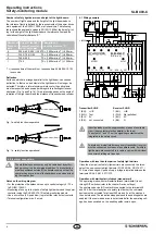
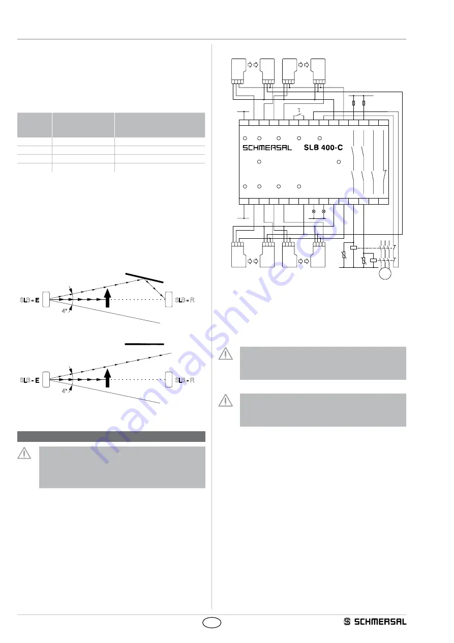
Deflection
Surfaces, which are arranged parallel to the light beam, can cause a
deflection. In that case, a obstacle in the light beam will no longer be
detected. Therefore, a lateral minimum distance for the optical axis
must be respected and observed with regard to reflecting surfaces or
obstacles. (Fig. 1a and Fig. 1b). This distance depends on the angle of
radiation of the light barrier and the distance of transmitter and receiver.
4°
SLB - E
SLB - R
Fig. 1a: safety function inoperative
4°
SLB - E
SLB - R
Fig. 1b: safety function operational
4. Electrical connection
The electrical connection may only be carried out by author-
ised personnel in a de-energised condition. The reset button
must be positioned outside of the hazardous area so that the
operator has an overview of the hazardous area when actuat-
ing the reset button.
Notes on the wiring diagram
• For the protection of hazardous areas up to control category 4 / PL e
to EN ISO 13849-1.
• Monitoring of one up to four pairs of safety light barriers and the power
contactor using the SLB 400-C10-1R safety-monitoring module.
• Use a micro-fuse (2 A quick blow) to protect the relay output contacts.
• Terminal configuration: max. 2 wired.
4.1 Wiring example
L1
K4
K5
+24 VDC
0 V
0 V
N
3 ~
M
X2
X1
A1
1 2 3 4
1 2 3 4
1 2 3 4
1 2 3 4
1 2 3 4
1 2 3 4
1 2 3 4
1 2 3 4
X3
X4
X7
X5
X6
X8
13
23
33
41
A2
0V
SLB-E
SLB-E
SLB-E
SLB-R
SLB-R
SLB-R
SLB-R
SLB-E
T3
Q3 T4
Q4
PM
INDIC.
U OUT
U OUT
B
B
Y1
Y2
-
-
+
+
X9
X10 X11 X12 X13 X14
14
24
34
42
24V T1
T2
Q1
Q2 RESTART CONT.M
Made in Germany
RESTART
RELAY
J
Transmitter SLB-E
Receiver SLB-R
1 (BN): +UB
1 (BN): +UB
2 (WH): Test
2 (WH): Qp (pollution)
3 (BU): 0V
3 (BU): 0V
4 (BK): not connected
4 (BK): Q
Inductive loads must be suppressed by means of a suitable
circuit (use contact protection parallel to the load).
The outputs Y1 and Y2 nor the signalling contacts must be
integrated in the safety circuit.
To avoid any mutual interference, every transmitter / receiver
must be connected by means of a separate cable. If multiple
light barriers are connected to a cable, a cable with individual
conductor shielding mut be used.
Operation with less than four pairs of safety light barriers
If less than four pairs of safety light barriers are connected, the termi-
nals of the non-connected light barriers (X1/X2, X3/X4, X9/X10, X11/
X12) must be bridged. Upon delivery, a bridge is installed between the
terminals X3/X4, X9/X10, X11/X12.
Operation with start/restart interlock (manual start)
The operating mode with start/restart interlock (start/restart) is set
through DIP switches (refer to the chapter Device settings).
The command device (NO contact) is connected to the terminals X5
and X6. After the interruption of a safety light barrier, the command
device must be actuated for at least 250 ms and 5 s at the most and
then be released. The indication disappears and the enabling paths are
enabled. If the command device is not actuated after the operating volt-
age has been switched on, the enabling paths remain open.

