2
Operating instructions
Safety-monitoring module
SLB 400-C
EN
1.6 Warning about misuse
In case of inadequate or improper use or manipulations of the
safety switchgear, personal hazards or damage to machin-
ery or plant components cannot be excluded. The relevant
requirements of the standards 13855 and DIN EN ISO 13857
must be observed.
1.7 Exclusion of liability
We shall accept no liability for damages and malfunctions resulting from
defective mounting or failure to comply with this operating instructions
manual. The manufacturer shall accept no liability for damages result-
ing from the use of unauthorised spare parts or accessories.
For safety reasons, invasive work on the device as well as arbitrary re-
pairs, conversions and modifications to the device are strictly forbidden;
the manufacturer shall accept no liability for damages resulting from
such invasive work, arbitrary repairs, conversions and/or modifications
to the device.
2. Product description
2.1 Ordering code
This operating instructions manual applies to the following types:
SLB 400-C10-1R
Only if the information described in this operating instruc-
tions manual are realised correctly, the safety function and
therefore the compliance with the Machinery Directive is
maintained.
2.2 Special versions
For special versions, which are not listed in the order code below 2.1,
these specifications apply accordingly, provided that they correspond to
the standard version.
2.3 Destination and use
In combination with one to four testable safety light barriers, SLB
400-E50-21P (transmitter) and SLB 400-R50-21P (receiver), the SLB
400-C10-1R safety-monitoring module is a non-contact safety guard to
IEC 61496, type 4, for the protection of hazardous areas on power-
driven work equipment.
The user must evaluate and design the safety chain in ac-
cordance with the relevant standards and the required safety
level.
2.4 Technical data
Standards:
EN 61496-1, DIN CLC/TS 61496-2,
EN ISO 13849-1
Start-up test:
yes
Start conditions:
Start-reset button, on/off coding
Feedback circuit:
yes
Enclosure:
glass-fibre reinforced thermoplastic
Mounting:
Snaps onto standard DIN rail to EN 50022
Termination:
Screw terminals
Cable section:
max. 4 mm²
(incl. conductor ferrules)
Protection class:
terminals IP20, enclosure IP40
U
e
:
24 VDC ± 15%
Max. fuse rating of the operating voltage:
1 A
I
e
:
0.3 A without additional transistor outputs and safety light
barriers
Inputs:
Monitored inputs
max. 4 pairs of light barriers
Input resistance:
approx. 2 kΩ to GND
Input signal „1“:
10 ... 30 VDC
Input signal „0“:
0 ... 2 VDC
Max. cable length:
100 m of 0.75 mm² conductor
Outputs:
2 enabling paths
Utilisation category:
AC-15, DC-13
I
e
/U
e
:
2 A / 250 VAC, 2 A / 24 VDC
Contact load capacity:
max. 250 VAC, max. 2 A (cos Ω = 1)
Switching voltage:
max. 250 VAC
Load current:
max. 2 A
Switching capacity:
max. 500 VA
Max. fuse rating:
2 A gG D-fuse
Signalling output:
2 transistor outputs, Y1 + Y2 = max. 100 mA, p-
type, short-circuit proof
Response time:
≤ 25 ms
EMC rating:
conforming to EMC Directive
Max. switching frequency:
10 Hz
Overvoltage category:
II to DIN VDE 0110
Degree of pollution:
3 to DIN VDE 0110
:
10 ... 55 Hz / amplitude 0.35 mm, ± 15 %
Resistance to shock:
30 g / 11 ms
Ambient temperature:
–20 °C … + 55 °C
Storage and transport temperature:
–25 °C … +70 °C
Dimensions:
99.7 x 75 x 110 mm
2.5 Safety classification
(in combination with the SLB 400-E/R50-21P safety light barriers)
Standards:
EN ISO 13849-1, IEC 61508
PL:
up to e
Control category:
up to 4
PFH-value:
- up to max. 100,000 switching cycles/year:
3,08 × 10
-8
/h at DC
2 A;
- up to max 50.000 switching cycles/year:
7,11 × 10
-8
/h at AC 2 A
SIL:
up to 3
Service life:
20 years
2.6 Basic principles for safe utilisation
Electrical influence of the machine or plant control system to be pro-
tected must be enabled.
A switching command from the safety-monitoring module must cause
the shutdown of the hazardous movement.
Settings and changes to the safety guard must only be carried out by
authorised expert staff.
It must be ensured that a person cannot reach the danger point of the
hazardous area before the hazardous movement has come to a stand-
still. As long as a person or a body part is within the danger point or the
hazardous area, the machine must not restart.
Actuation of command devices destined to the release of the machine
or plant from outside the hazardous area must be impossible. The
operator must have a complete overview of the hazardous area.
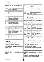
2.7 Functions
The safety-monitoring module has a dual-channel structure. It includes
two safety relays with monitored positive action contacts. The series-
wired NO contacts of the relays build the enabling paths. The safety-
monitoring module has inputs to monitor testable safety light barriers,
a start button, a feedback contact to monitor external contactors and
an input for the soiling outputs of the safety light barriers. The status of
these inputs is signalled by the yellow LED located next to the terminal.
The safety function of the entire system is automatically checked, after
each switch-on of the ESD and each manual test request (external test
signal by actuation of the corresponding command device). In addition
to that, a cyclic test is performed during operation.

