5
SLB 400-C
Operating instructions
Safety-monitoring module
EN
If it is possible to leave the hazardous area in the direction of the dan-
ger point, it is imperative to choose an operation with restart interlock.
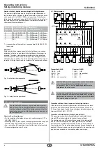
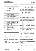
4.2 Wiring
Pin
Function/connection
A1
+U
B
operating voltage SLB 400-C
A2
–U
B
operating voltage SLB 400-C
+
+U
B
operating voltage SLB 400 E/R
–
–U
B
operating voltage SLB 400 E/R
13-14
Enabling path
23-24
Enabling path
Light barriers
X1
Connection test input light barrier 1
X2
Connection switching output light barrier 1
X3
Connection test input light barrier 2
X4
Connection switching output light barrier 2
X9
Connection test input light barrier 3
X10
Connection switching output light barrier 3
X11
Connection test input light barrier 4
X12
Connection switching output light barrier 4
Signalling outputs
33-34
Signalling contact enabling path closed (NO contact)
41-42
Signalling contact enabling path opened (NC contact)
X5
Start/restart button (NO contact) connection,
voltage tap +24 V DC
X6
Start/restart button (NO contact) connection, input
X7
Feedback circuit connection, voltage tap +24 V DC
X8
Feedback circuit connection, input
X14
Signal input, safety light barrier(s)
soiled
Y1
Signal output, enabling request of the
start/restart interlock
Y2
Signal output, safety light barrier(s)
soiled
5. Set-up and maintenance
5.1 Functional testing
The safety function of the safety components must be tested. The fol-
lowing conditions must be previously checked and met:
1. Correct assembly of the safety light barriers
2. Check the integrity of the cable entry and connections.
3. Check the safety light barrier's and the safety-monitoring module's
enclosure for damage.
4. If one or more light barriers are interrupted, the hazardous movement
is brought to standstill
5. The safety distance of the application exceed the mathematically
calculated one.
5.2 Diagnostic
LED display
The LED indication of the safety-monitoring module shows the different
switching conditions and errors. The switching conditions are explained
in the table.
LED
Colour
Function
Power
green
LED is on, when the operating voltage is cor-
rectly connected.
Restart
yellow
LED is on, when the actuation of the com-
mand device (start/restart button) by the
operator is requested. The LED stays on, until
the button has been correctly (incl. times)
actuated.
Input
LED`s
yellow
LED's are on, when a positive voltage is
present at the corresponding input terminal.
RELAY
green
Enabling paths closed
(system ready for operation and clear)
red
(perma-
nently)
Enabled paths opened
(system ready for operation, however not
clear)
red
(flashing)
System error
(flash code, refer to paragraph "Diagnostic")
Integral system diagnosis (ISD)
In case of error messages, the "RELAY" LED of the safety-monitoring
module lights intermittently red. During these intermissions, the LED
flashes one up to six times with short pulses. The possible errors and
their causes are listed in the following table.
Display
Error
Cause
one impulse Short-circuit Short-circuit in the cable, the test inputs
of the light barriers, the contacts of
the contactor control, the button of the
restart interlock.
two im-
pulses
Contactor
control
The contactor control is disabled through
the DIP switches and there is a positive
signal at the input.
three im-
pulses
DIP-
switch
The restart interlock or the bit pattern set
is not set with a dual-channel structure at
the DIP switch.
four im-
pulses
Relay
Error of the internal relays or their con-
trol, supply voltage too low.
five im-
pulses
Interference
signals
Too high inductive or capacitive interfer-
ences on the connecting cables
six impulses internal
error
Error at an input circuit or processor
error
Deleting the error message
The error message is deleted, when the error cause is eliminated and
the protection field of at least one light barrier has been interrupted.
5.3 Maintenance
A regular visual inspection and functional test, including the following
steps, is recommended:
1. Check the correct fixation of the safety light barriers
2. Clean the optics of the transmitter and the receiver with a soft, clean
cloth. The use of agressive, abrasive or scratching cleaning agents,
which could attack the surface, is prohibited.
3. The total response time of the machine does not exceed the re-
sponse time calculated during the first putting into operation.
6. Disassembly and disposal
6.1 Disassembly
The safety switchgear must be disassembled in a de-energised condi-
tion only.
6.2 Disposal
The safety switchgear must be disposed of in an appropriate manner in
accordance with the national prescriptions and legislations.

