5
SLB240
Operating instructions
Safety light barriers
EN
Activating alignment mode with 5-pole cable connection
If through power-up 24V is applied to the restart input via a pushbutton
for at least 2 seconds the device will start in alignment mode The push
button can be released as soon as the indicator changes from red to
yellow
Activating setup mode with 4-pole cable connection
If +24V is applied for at least 2 seconds when the system starts at the
"OSSD 1" output, the receiver unit starts in alignment mode
If setup mode is activated with 24V at OSSD 1, the outputs
OSSD 1 and OSSD 2 must not be connected to the machine
or the machine controls
Activating setup mode with adapter cable KA-0977
Connect the adapter cable to the device Press and hold the integrated
button and switch the supply voltage on The button can be released as
soon as the indicator changes from red to yellow
3.5 Safety distance
The safety distance is the minimum distance between the protection
field of the safety light barrier and the hazardous area The safety
distance must be observed to ensure that the hazardous area cannot
be reached before the hazardous movement has come to standstill
Calculation of the safety distance to EN ISO 13855 and EN ISO 13857
The safety distance depends on the following elements:
• Stopping time of the machine (calculation by run-on time
measurement)
• Response time of the machine and the safety light barrier and the
downstream safety-monitoring module (entire safety guard)
• Approach speed
Safety light barrier
The safety distance for the safety light barrier is calculated by means of
the following formula:
S = (1600 mm/s x T)+ 1200 [mm]
S = Safety distance [mm]
T = Total reaction time (machine run-on time,
reaction time of the safety guard, relays, etc)
To prevent the AOPD from reaching over or creeping under, the beam
should be installed 750 mm above the ground or reference level
(see ISO 13857)
If using safety light barriers, the following points must be observed:
• Prevent the possibility of going under or over the beam
• Prevent the possibility of reaching through between two beams
• Prevent the possibility of climbing through between two beams
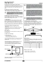
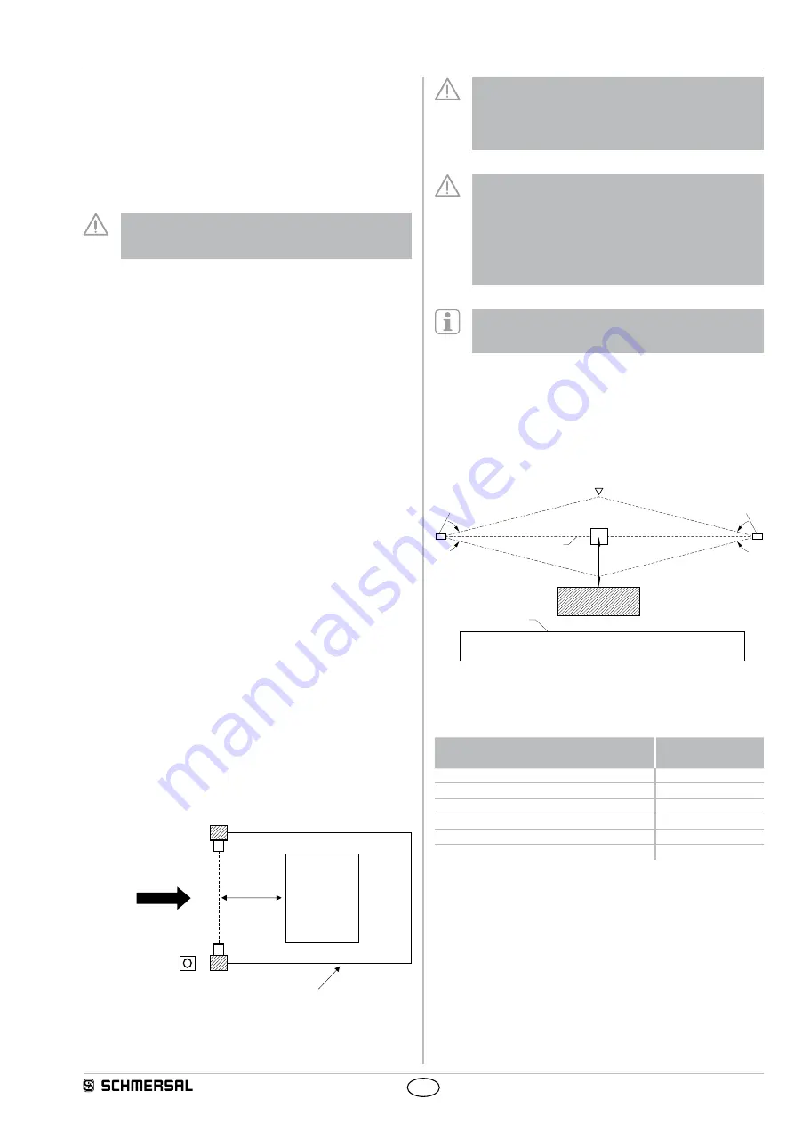
Safety distance to the hazardous area
S
Hazardous
point
Transmitter
Receiver
Command device
Authorised operation
Mechanical protection
Direction from which the
hazardous area is accessed
Please observe the applicable harmonised EN standards and possible
applicable national regulations
The safety distance between the safety light barrier and the
hazardous point must always be respected and observed If
a person reaches the hazardous point before the hazardous
movement has come to a standstill, he or she is exposed to
serious injuries
The AOPD should be located parallel with the floor and the
beam should be interrupted by the upright body of a person
A single beam AOPD as the only guard system is not suitable
for preventing the whole body of a person from accessing
We recommend combining the AOPD with other protective
equipment to make it impossible to pass by the guard system
without being detected in the process The AOPD can not be
used as finger or hand protection
To calculate the minimum distances of the safety guards
with regards to the hazardous point, the EN ISO 13855 and
EN ISO 13857 must be observed
3.5.1 Minimum distance to reflecting surfaces
During the installation, the effects of reflecting surfaces must be taken
into account In case of an incorrect installation, interruptions of the
protection field could possibly not be detected, which could lead to
serious injuries The hereafter-specified minimum distances with regard
to reflecting surfaces (metal walls, floors, ceilings or parts) must be
imperatively observed
8°
8°
a= 262 mm
Access direction
Receiver
Obstacle
Optical axis
Transmitter
Reflecting body
(eg Material container)
Limit of the
hazardous point
a=262mm
5°
5°
Minimum distance a
Calculate the minimum distance to reflecting surfaces as a function of
the distance with an aperture angles of ± 5° degrees or use the value
from the table below:
Distance between transmitter and receiver
[m]
Minimum distance
a [mm]
02 … 30
262
4
350
5
440
7
620
10
880
12
1060
Formula: a = tan 5° x L [mm]
a = Minimum distance to reflecting surfaces
L = Distance between transmitter and receiver

