7
SLB240
Operating instructions
Safety light barriers
EN
Connecting cable for emitter / receiver (4-pole)
Item N
o
Designation Description
Length
101207741 KA-0804
Female connector M12, 4-pole 5 m
101207742 KA-0805
Female connector M12, 4-pole 10 m
101207743 KA-0808
Female connector M12, 4-pole 20 m
Connecting cable for receiver (5-pole)*
Item N
o
Designation
Description
Length
101209949 A-K5P-M12-S-G-
5M-BK-2-X-A-1
Female connector M12,
5-pole
5 m
101209948 A-K5P-M12-S-G-
15M-BK-2-X-A-1
Female connector M12,
5-pole
15 m
* For use in the operating mode Restart Interlock (manual reset)
Adapter cable for parameter setting
Item N
o
Designation Description
Length
103013625 KA-0977
Pushbutton with
command device
1x male connector M12, 5-pole
2x female connector M12, 5-pole
3 m
4. Electrical connection
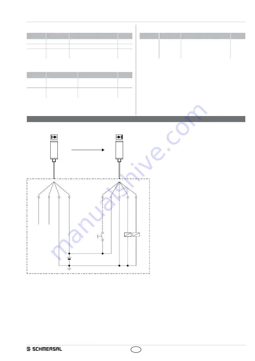
4.1 Wiring example SLB240
S 1
K 1
K 2
5
1
3
2
4
E 1
2
4
1
3
Not connected (BK)
Test (WH)
OSSD 2 (BK)
0 VDC (BU)
+24 VDC (BN)
Release restart (GY)
+24 VDC (BN)
0 VDC (BU)
OSSD 1 (WH)
Earth connection
Protective mode / Automatic active:
Delivery state (Command device button S1 not connected)
Restart Interlock (manual reset) active:
Refer to the chapter: operating mode activate restart interlock
(Command device button 1 connected)
K1, K2:
Relay for processing the switching outputs
OSSD 1,OSSD 2
S1:
Command device pushbutton for restart
(optional)
E1:
Power supply 24 VDC ± 10%

