background image

EN

Operating instructions           pages 1 to 12

Original

SLB440

SLB450

Operating instructions

Safety light barriers

EN

1

1. About this document

1.1  Function

This operating instructions manual provides all the information you 

need for the mounting, set-up and commissioning to ensure the 

safe operation and disassembly of the safety device The operating 

instructions must be available in a legible condition and a complete 

version in the vicinity of the device

1.2  Target group: authorised qualified personnel

All operations described in this operating instructions manual must 

be carried out by trained specialist personnel, authorised by the plant 

operator only

Please make sure that you have read and understood these operating 

instructions and that you know all applicable legislations regarding 

occupational safety and accident prevention prior to installation and 

putting the device into operation

The machine builder must carefully select the harmonised standards 

to be complied with as well as other technical specifications for the 

selection, mounting and integration of the components

1.3  Explanation of the symbols used

Information, hint, note:

This symbol is used for identifying useful additional information

Caution:

 Failure to comply with this warning notice could 

lead to failures or malfunctions

Warning:

 Failure to comply with this warning notice could 

lead to physical injury and/or damage to the machine

Content

About this document

11  Function                                            1

12 

Target group: authorised qualified personnel

                 1

13  Explanation of the symbols used                         1

14  Appropriate use                                      2

15  General safety instructions                               2

16  Warning about misuse                                 2

17  Exclusion of liability                                    2

Product description

21  Purpose and use                                      2

22  Ordering code                                        2

23  Special versions                                       2

24  Included in delivery                                    2

25  Technical data                                        3

26  Response time (reaction time)                            3

27 

Safety classification

                                   3

28  Modes of operation / functions                            3

281  Protection mode with automatic (automatic)                 3

282 Protection mode with restart interlock                      4

283 Parameter setting                                      4

284 Self-test                                             4

Mounting

31  General conditions                                     5

32 

Protection field and approach

                            5

33  Aligning the sensors                                    5

34  Alignment mode                                       5

35  Safety distance                                        6

351 

Minimum distance to reflecting surfaces

                   6

36  Interference / Beam coding                              7

37  Dimensions                                          7

38  Mounting material (Not included in delivery!)                 8

Electrical connection

41  Wiring example SLB440                                 9

42  Wiring example SLB450                                 9

43 

Connector configuration Receiver, Transmitter & Cable

      10

431 SLB440                                            10

432 SLB450                                            10

Set-up and maintenance

51  Check before start-up                                  10

52  Maintenance                                         10

53  Regular check                                       10

54  Half-yearly inspection                                   11

55  Cleaning                                             11

Diagnostic

61 

Indication of configuration when system starts

               11

62  Status display                                         11

63  Error indication                                        11

Disassembly and disposal

71  Disassembly                                          11

72  Disposal                                            11

Appendix

81  Contact                                              11

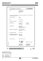
EU Declaration of conformity

x

000 / 10

2016 / v

A

   -   103014467-EN / 

A / 2016-10-21 / 

AE-Nr

 -

Summary of Contents for SLB440

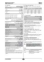
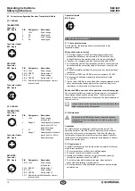
Page 1: ...d lead to physical injury and or damage to the machine Content 1 About this document 1 1 Function 1 1 2 Target group authorised qualified personnel 1 1 3 Explanation of the symbols used 1 1 4 Appropri...

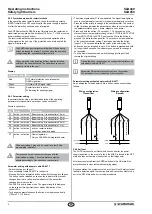
Page 2: ...ents cannot be excluded when safety device is used The relevant requirements of the standards EN ISO 13855 EN ISO 13857 must be observed Only if the information described in this operating instruction...

Page 3: ...ailure OSSD leakage current The downstream control element must recognise this state as LOW A safety PLC must detect this state 4 The load inductivity generates an induced voltage during the switch of...

Page 4: ...e released as soon as the indicator of the receiver changes from red to yellow and the indicator of the transmitter changes from blue to yellow The AOPD is now in setup mode The signal strength is dis...

Page 5: ...light impulses The better the alignment the higher the frequency of the light pulses The alignment is optimal when the light pulses switch over to continuous light If there is no optical synchronisati...

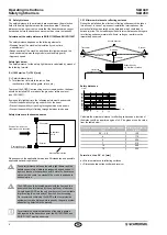
Page 6: ...fety distance between the safety light barrier and the hazardous point must always be respected and observed If a person reaches the hazardous point before the hazardous movement has come to a standst...

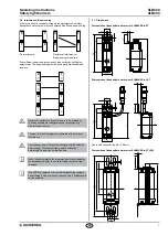
Page 7: ...at risk if systems are operated with reciprocal interference The response time of the system changes with the selected beam coding The safety distance must be adapted accordingly See section on reacti...

Page 8: ...5 m For use in the operating mode Restart Interlock manual reset Adapter cable for parameter setting Item No Designation Description Length 103013625 KA 0977 Pushbutton with command device 1x male con...

Page 9: ...e 1 BK Range 2 WH OSSD 2 BK 0 VDC BU 24 VDC BN Release restart GY 24 VDC BN 0 VDC BU OSSD 1 WH Earth connection S 1 K1 K2 5 1 3 2 4 E1 2 4 1 3 Protective mode Automatic active Delivery state Command d...

Page 10: ...d The operating principle of the AOPD and the machine must be known in order to be able to conduct an inspection If the fitter the planning technician and the operator are different persons please mak...

Page 11: ...ver the indicator is delayed until there is no change in the ON state or OFF state of the OSSDs for 5 seconds Only SLB450 transmitter If the transmitter is configured for alternative range an addition...

Page 12: ...n of the technical documentation Oliver Wacker M ddinghofe 30 42279 Wuppertal K A Schmersal GmbH Co KG M ddinghofe 30 D 42279 Wuppertal Postfach 24 02 63 D 42232 Wuppertal Phone 49 0 2 02 64 74 0 Tele...

Reviews: