10
Operating instructions
Safety light barriers
SLB440
SLB450
EN
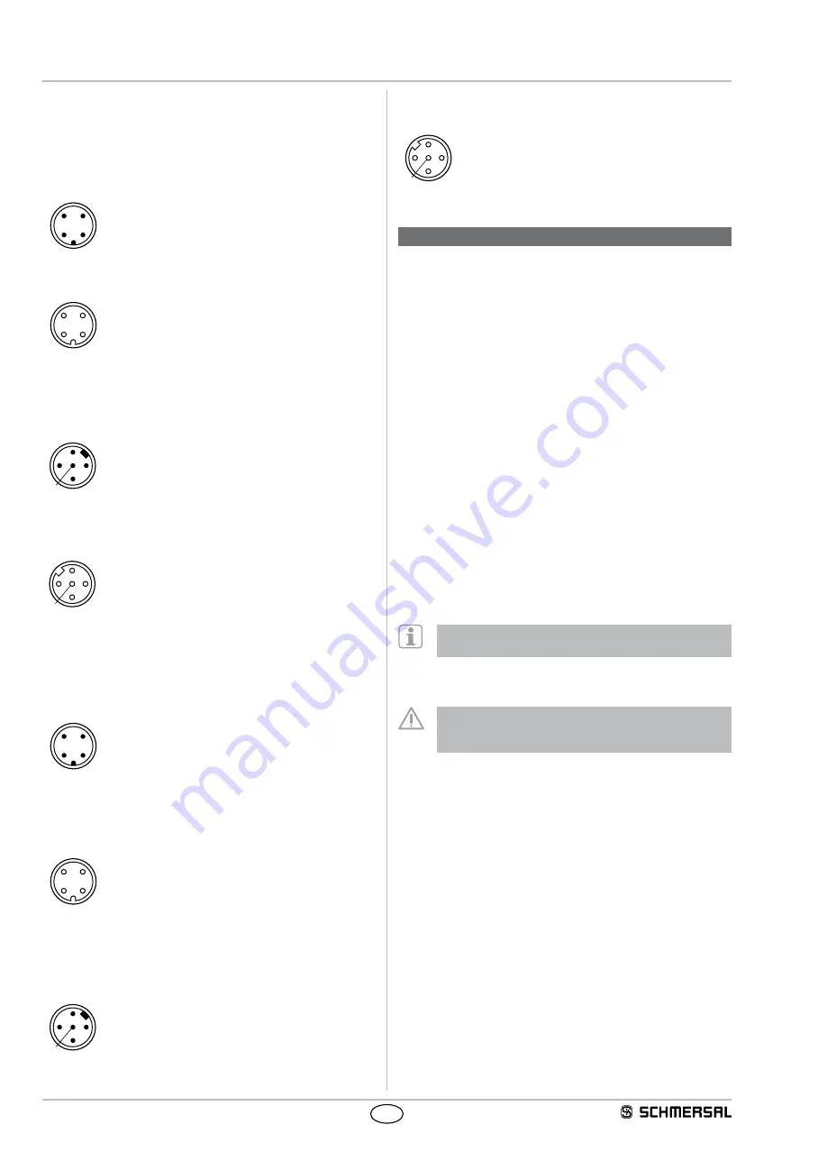
Connector female
M12, 5-pole
3
2
5
1
4
5. Set-up and maintenance
5.1 Check before start-up
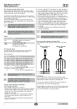
Prior to start-up, the following items must be checked by the
responsible person
Wiring check prior to start-up
1 The voltage supply is a 24V direct current power supply (see
technical specifications), which meets the CE Directives, Low
Voltage Directives A power downtime of 20 ms must be bridged
2 Presence of a voltage supply with correct polarity at the AOPD
3 The connecting cable of the transmitter is correctly connected to the
transmitter and the connecting cable of the receiver correctly to the
receiver
4 The double insulation between the output and an external potential
is assured
5 The outputs OSSD1 and OSSD2 are not connected to +24 VDC
6 The connected switching elements (load) are not connected
to +24 VDC
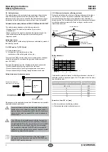
7 If two or more AOPDs are used within close range compared to each
other, an alternating arrangement must be observed Any mutual
interference of the systems must be prevented
Switch the AOPD on and check the operation in the following way:
The component performs a system test during approx 2 seconds after
the operating voltage has been switched on The outputs are then
enabled if the protection field is not interrupted The status indication at
the receiver is on
In case of incorrect functionality, please follow the instructions
listed in the chapter Fault diagnostic
5.2 Maintenance
Do not use the AOPD before the next inspection has been
completed An incorrect inspection can lead to serious and
mortal injuries
Conditions
For safety reasons, all inspection results must be archived The
operating principle of the AOPD and the machine must be known in
order to be able to conduct an inspection If the fitter, the planning
technician and the operator are different persons, please make sure
that the user has the necessary information at his disposal to be able
conduct the maintenance
5.3 Regular check
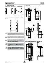
A regular visual inspection and functional test, including the following
steps, is recommended:
1 The component does not have any visible damages
2 The optics cover is not scratched or soiled
3 Hazardous machinery parts can only be accessed by passing
through the protection zone of the AOPD
4 The staff remains within the detection area, when works are
conducted on hazardous machinery parts
5 The safety distance of the application exceeds the mathematically
calculated one
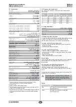
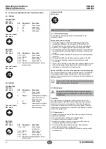
4.3 Connector configuration Receiver, Transmitter & Cable
4.3.1 SLB440
TRANSMITTER
Connector
M12, 4-pole
PIN
Designation
Description
3
2
1
4
1
+24 V
Power supply
2
NC
Unassigned
3
0 V
Power supply
4
NC
Unassigned
Connector female
M12, 4-pole
3
2
1
4
RECEIVER
Connector
M12, 5-pole
PIN
Designation
Description
3
2
5
1
4
1 BN +24 V
Power supply
2 WH OSSD1
Safety output 1
3 BU 0 V
Power supply
4 BK OSSD2
Safety output 2
5 GY Restart interlock
(manual reset)
Authorisation / restart
Connector female
M12, 5-pole
3
2
5
1
4
4.3.2 SLB450
TRANSMITTER
Connector
M12, 4-pole
PIN
Designation
Description
3
2
1
4
1
+24 V
Power supply
(with heater)
2
Range 2
Unassigned for standard,
must be set to 0V for
alternative range
3
0 V
Power supply
4
Range 1
Unassigned for standard,
must be set to +24V for
alternative range
Connector female
M12, 4-pole
3
2
1
4
RECEIVER
Connector
M12, 5-pole
PIN
Designation
Description
3
2
5
1
4
1 BN +24 V
Power supply
(with heater)
2 WH OSSD1
Safety output 1
3 BU 0 V
Power supply
4 BK OSSD2
Safety output 2
5 GY Restart interlock
(manual reset)
Authorisation / restart


