3
SLB440
SLB450
Operating instructions
Safety light barriers
EN
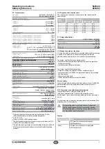
2.5 Technical data
Standards:
EN 61496-1; EN 61496-2;
EN ISO 13849; EN 62061
Material of the enclosure:
Aluminium
Detection ability for test bodies:
- SLB440:
10 mm static
1)
- SLB450:
10 mm static
1)
Alternative range:
70 mm static
1)
SLB range:
- SLB440:
03 … 150 m
- SLB450:
03 … 180 m
Alternative range:
12 … 75 m
Reaction time:
- Beam coding 1, impulse pattern 1, 5 samplings:
10 ms
- Beam coding 2, impulse pattern 2, 5 samplings:
14 ms
- Beam coding 3, impulse pattern 3, 5 samplings:
18 ms
- Beam coding 4, impulse pattern 4, 5 samplings:
22 ms
- Beam coding 5, impulse pattern 1, 3 samplings:
7 ms
Rated operating voltage:
- SLB440/450:
24 VDC ± 10%, 1 A
- SLB450-EH:
24 VDC +10%, controllable output voltage, 4 A
PELV mains unit in accordance with EN 60204
(power failure bypass 20 ms)
Rated operating current:
- SLB440/450:
100 mA + 2x 200 mA each OSSD
- SLB450-EH:
3 A + 2x 200 mA each OSSD
Wavelength of the infrared radiation:
880 nm
Transmitter, infrared emitted radiation
- to DIN EN 12198-1:
Category 0
- to DIN EN 62471:
free group
Safety outputs
OSSD1, OSSD2:
2 x short-circuit proof PNP
semi-conductor outputs
Test impulse cycle OSSD:
600 ms
Test impulse length:
max 200 µs
Switching voltage HIGH
2)
:
>15 V
Switching voltage LOW
2)
:
<2 V
Switching current each OSSD:
200 mA
Leakage current
3)
:
<1 mA
Load capacity:
max 200 nF
Load inductance
4)
:
max 2 H
Inputs:
- SLB440/450:
restart 100 ms to 1500 ms monitored
Function:
Protective mode / Automatic,
Restart Interlock (manual reset),
Setting mode
Status indication receiver:
End cap with integrated
status indication
Connection:
- Transmitter:
connector M12, 4-pole
- Receiver:
connector M12, 5-pole
Ambient temperature:
−30° C … + 50° C
Storage temperature:
−30° C … + 70° C
Protection class:
IP67 (IEC 60529)
Resistance to vibration:
10 … 55 Hz to IEC 60068-2-6
Resistance to shock:
10 g, 16 ms, to IEC 60028-2-29
Year of construction:
as of 2016 version 10
1)
Detection capability is reduced with moving test body Further
information available from technical sales department
2)
To IEC 61131-2
3)
In case of failure, OSSD leakage current
The downstream control element must recognise this state as LOW
A safety PLC must detect this state
4)
The load inductivity generates an induced voltage during the switch-off,
which compromises the downstream components (spark quenching
element)
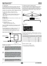
2.6 Response time (reaction time)
The response time depends on the number of light beams and the
beam coding A
Beam
coding
Response
time [ms]
Weight [kg]
SLB440-ST SLB440-LST SLB450
1
10
014
015
04
2
14
014
015
04
3
18
014
015
04
4
22
014
015
04
5
7
014
015
04
2.7 Safety classification
Standards:
EN ISO 13849-1, EN 62061
PL:
up to e
Control category:
up to 4
PFH:
15 x 10
-8
1/h
SIL:
up to 3
Service life:
20 years
2.8 Modes of operation / functions
All of the described functions can be executed without safety monitoring
modules A command unit is needed for diagnosis and function
selection (button, adapter cable, see section on parameterisation)
The system has the following operating modes:
• Protection mode with automatic start after release of the protection
field (factory setting)
• Protection mode with restart interlock
The system has the following functions:
• Parameter setting with selection of beam coding and type of
protection mode On SLB450, the integrated heater can be activated
and deactivated
• Alignment aid, diagnosis
• Heater with temperature control (only SLB450)
Factory setting
When delivered (factory setting) automatic mode is active On SLB450
with integrated heater, the heater/temperature control is active in
delivered state
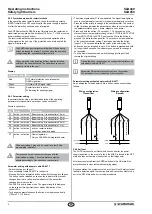
2.8.1 Protection mode with automatic (automatic)
In automatic mode the safety switching outputs
(OSSD) are switched to the ON state if the protection zone is
uninterrupted This is done without any authorization from a command
device
This operating mode initiates an automatic restart of the machine if the
protection zone is not interrupted
This operating mode may only be chosen in conjunction
with the restart interlock (manual reset) of the machine
This operating mode must not be chosen, when persons
can step behind the protection field
Display
Diagnostic lamp Status
Red
OFF state (protection zone interrupted,
OSSD signal low)
Green
ON state (protection zone uninterrupted,
OSSD signal high)


