8
Operating instructions
Safety light barriers
SLB440
SLB450
EN
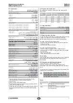
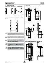
3.8 Mounting material (Not included in delivery!)
Mounting kit MS-1101 (only SLB440)
The mounting kit consists of 2 steel angles and 4 fixing screws (Type
Torx plus 10IP)
5,5
17
28
24
7
11
24
38
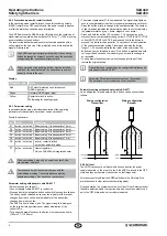
Mounting kit MS-1030 (only SLB450)
The mounting kit consists of 4 steel angles and 16 fixing screws
14,5
42
18,9
20
6,5
40
32
52
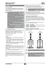
Connecting cable for emitter / receiver (4-pole)
Item N
o
Designation Description
Length
101207741 KA-0804
Female connector M12, 4-pole 5 m
101207742 KA-0805
Female connector M12, 4-pole 10 m
101207743 KA-0808
Female connector M12, 4-pole 20 m
Connecting cable for receiver (5-pole)*
Item N
o
Designation
Description
Length
101209949 A-K5P-M12-S-G-
5M-BK-2-X-A-1
Female connector M12,
5-pole
5 m
101209948 A-K5P-M12-S-G-
15M-BK-2-X-A-1
Female connector M12,
5-pole
15 m
* For use in the operating mode Restart Interlock (manual reset)
Adapter cable for parameter setting
Item N
o
Designation Description
Length
103013625 KA-0977
Pushbutton with
command device
1x male connector M12, 5-pole
2x female connector M12, 5-pole
3 m
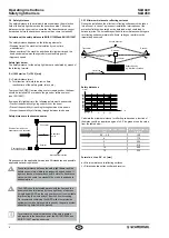
Electric heater (only SLB450-ER-x-ST-EH)
Recommended wiring for SLB450 with electric heater:
• Max cable length: 20 m
• Cable cross section up to 25 m: 15 mm² -
installation with +24V and 0V
• Cable cross section 25 m to 75 m: 2 x 15 mm² / 1 x 40 mm² -
installation with +24V and 0V
At larger distances (>15 m), it is recommended to supply both sensors
of the AOPD with separate power supplies to keep the cable lengths
short
Following installation, the operating voltage must be measured at
the last terminal to the heater If the operating voltage is outside the
specification, this is indicated by a "flashing white" status signal In this
case, the operating voltage must be adjusted
Power supply is to be dimensioned with sufficient reserve and should
have a capacity of 3 A per device or 4 A for both


