background image

10

EN

SLC 430

Operating instructions

Safety light curtain

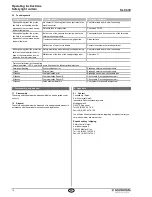
6.3  Fault diagnostic

Failure/malfunction

Possible causes

Check and elimination

Although being clear, the protec-
tion field is not enabled after the 
actuation of the command device, 
indicator lamp green

No contact of the wiring from the output relay to the 
machine control

Check terminals and re-wire if necessary

Defective fuse in output relay

Check fuse F5/F6

Although being clear, the protec-
tion field is not enabled after the 
actuation of the command device, 
indicator lamp red

Both or one of the sensors incorrectly wired to the 
safety-monitoring module

Check polarity and bus connection of the terminals

Translucent surface of the sensors highly soiled

Clean surface

Malfunction of one or more beams

Contact the customer service department

Although being clear, the protection 
field is not enabled after the actu-
ation of the command device, no 
indication from indicator lamp

Safety-monitoring module's supply voltage missing

Check terminals and re-wire if necessary

Malfunction of the fuse of the supply voltage input

Check fuse F1

Protection field clear, but no enabling
Normal operation - LED 5 (red) emits every 3 seconds the following flash impulses
Permanent flashing

Synchronisation error

Exchange safety-monitoring module

1 flash

Error self-test

Exchange safety-monitoring module

2 flashes

Communication error

Exchange sensor pair, check cable pair

3 flashes

Communication Sensor E

Check cable E, exchange sensor pair

4 flashes

Communication Sensor R

Check cable R, exchange sensor pair

5 flashes

False plant parameters

Check plant components assignment

7.  Disassembly and disposal

7.1  Disassembly

The safety switchgear must be disassembled in a de-energised condi-

tion only.

7.2  Disposal

The safety switchgear must be disposed of in an appropriate manner in 

accordance with the national prescriptions and legislations.

8.  Appendix

8.1  Contact

Consultancy / Sales:

K.A. Schmersal GmbH

Industrielle Sicherheitsschaltsysteme

Möddinghofe 30

D-42279 Wuppertal

Tel:+49 (0) 202 64 74 -0 

Fax:+49 (0) 202 64 74- 100

You will also find detailed information regarding our product variety on 

our website: www. schmersal.com

Repair handling / shipping:

Safety Control GmbH

Am Industriepark 11

D-84453 Mühldorf / Inn

Tel.: +49 (0) 8631-18796-0

Fax: +49 (0) 8631-18796-1

Summary of Contents for SLC 430

Page 1: ...ith this warning notice could lead to physical injury and or damage to the machine 1 4 Appropriate use The products described in these operating instructions are developed to execute safety related fu...

Page 2: ...field heights in mm available lengths 0236 0460 0684 0908 1132 1356 1580 1804 Only if the information described in this operating instructions manual are realised correctly the safety function and th...

Page 3: ...only be cancelled after the protection field is enabled and an external command device has been actuated To switch between normal and hold operation restart interlock a slide switch on the control uni...

Page 4: ...ad and foot positions of both edges swapped The connector plugs are located at the head end of both sensors and therefore must point in the same direction the common direction however is not impor tan...

Page 5: ...lculation examples are related to the vertical set up refer to drawing of the light curtain with regard to the hazardous point Please observe the applicable harmonised EN standards and possible applic...

Page 6: ...460 30 RF 460 691 5 0 4 SLC 430 E R0684 30 RF 684 915 5 0 55 SLC 430 E R0908 30 RF 908 1139 5 0 65 SLC 430 E R1132 30 RF 1132 1363 5 0 8 SLC 430 E R1356 30 RF 1356 1587 5 0 9 SLC 430 E R1580 30 RF 158...

Page 7: ...carrying capacity is 4 A 250 VAC Both safety outputs must not be wired in series They must be wired 2 channel to the machi ne control In addition to both main outputs output 1 output 2 a signalling ou...

Page 8: ...on It must be impossible to restart the hazardous parts before the BWS has completely returned to its normal state and the machine control elements have been reactuated 3 Check the machine to ensure t...

Page 9: ...ansmitter ON orange Sensor E active 6 2 Optical and acoustic signals in the control unit The control unit includes an acoustic signal generator buzzer as well as multiple LED s The LED s n 1 2 and 3 g...

Page 10: ...he fuse of the supply voltage input Check fuse F1 Protection field clear but no enabling Normal operation LED 5 red emits every 3 seconds the following flash impulses Permanent flashing Synchronisatio...

Page 11: ...on authorised for the compilation of the tech nical documentation Ulrich Loss M ddinghofe 30 42279 Wuppertal Notified body for the prototype test T V Nord Cert GmbH Langemarckstr 20 45141 Essen ID n 0...

Page 12: ...Safety Control GmbH Am Industriepark 33 D 84453 M hldorf Inn Telefon 49 0 86 31 187 9 60 Telefax 49 0 86 31 187 9 61 E Mail info safetycontrol com...

Reviews: