2
EN
SLC 430
Operating instructions
Safety light curtain
The safety switchgear must exclusively be used in accordance with the
versions listed below or for the applications authorised by the manufac-
turer. Detailed information regarding the range of applications can be
found in the chapter "Product description".
1.5 General safety instructions
The user must observe the safety instructions in this operating instruc-
tions manual, the country-specific installation standards as well as all
prevailing safety regulations and accident prevention rules.
Further technical information can be found in the Schmersal
catalogues or in the online catalogue on the Internet: www.
schmersal.net.
The information contained in this operating instructions manual is provi-
ded without liability and is subject to technical modifications.
The entire concept of the control system, in which the safety
component is integrated, must be validated to EN ISO 13849-
2.
There are no residual risks, provided that the safety instructions as well
as the instructions regarding mounting, commissioning, operation and
maintenance are observed.
Additional measures could be required to ensure that the electro-sensi-
tive device does not present a dangerous breakdown, when other forms
of light beams are available in a special application (e.g. use of wireless
control devices on cranes, radiation of welding sparks or effects of
stroboscopic lights).
1.6 Warning about misuse
In case of inadequate or improper use or manipulations of the
safety switchgear, personal hazards or damage to machi-
nery or plant components cannot be excluded. The relevant
requirements of the standards EN ISO 13855 (successor of
EN 999) and EN ISO 13857 must be observed.
1.7 Exclusion of liability
We shall accept no liability for damages and malfunctions resulting from
defective mounting or failure to comply with this operating instructions
manual. The manufacturer shall accept no liability for damages resul-
ting from the use of unauthorised spare parts or accessories.
For safety reasons, invasive work on the device as well as arbitrary re-
pairs, conversions and modifications to the device are strictly forbidden;
the manufacturer shall accept no liability for damages resulting from
such invasive work, arbitrary repairs, conversions and/or modifications
to the device.
2. Product description
2.1 Ordering code
This operating instructions manual applies to the following types:
SLC 430-E/R➀-30-RF-SYS
No. Option
Description
➀
xxxx
Protection field heights in mm available
lengths:
0236, 0460, 0684, 0908,
1132, 1356, 1580, 1804
Only if the information described in this operating instructions
manual are realised correctly, the safety function and therefo-
re the compliance with the Machinery Directive is maintained.
2.2 Special versions
For special versions, which are not listed in the order code below 2.1,
these specifications apply accordingly, provided that they correspond to
the standard version.
2.3 Included in delivery and accessories
2.3.1 Accessories included in delivery
Sensor E and sensor R with mounting accessories,
Safety monitoring module NSR-0605,
Cable set KA-0610 (cable length 5 m)
2.3.2 Optional accessory
Connecting cable for emitter and receiver
Item num-
ber
Description
Description
Length
1207718
KA-0610
Female connector M8, 4-pole 5 m
1207719
KA-0611
Female connector M8, 4-pole 10 m
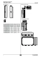
Profile for emitter/receiver
Item num-
ber
Description
Profile 40 x 40 mm
Length
1207720
MS-1501
SLC 430-E/R0236-30
467.5 mm
1207721
MS-1502
SLC 430-E/R0460-30
691.5 mm
1207722
MS-1503
SLC 430-E/R0684-30
915.5 mm
1207723
MS-1504
SLC 430-E/R0908-30
1139.5 mm
1207724
MS-1505
SLC 430-E/R1132-30
1363.5 mm
1207725
MS-1506
SLC 430-E/R1356-30
1587.5 mm
1207726
MS-1507
SLC 430-E/R1580-30
1811.5 mm
1207727
MS-1508
SLC 430-E/R1804-30
2035.5 mm
2.4 Destination and use
The SLC is a non-contact, self-testing safety guard, which is used for
the protection of hazardous points, hazardous areas and machine
access . If one or more light beams are interrupted, the hazardous
movement must be stopped.
The user must evaluate and design the safety chain in ac-
cordance with the relevant standards and the required safety
level.
2.5 Technical data
Standards:
EN 61496-1; CLC/TS 61496-2;
EN ISO 13849; EN 62061
Material of the enclosure:
Aluminium
Number of beams:
8 … 64 beams
Protection field heights:
236 mm - 1804 mm
Detection ability for test bodies:
30 mm
Range of the protection field:
0.2 … 3.5 m
Response time:
50 ms
Rated operating voltage:
22-30 VDC or 18-25 VAC
Operating current:
< 300 mA
Wave length of the sensor:
880 nm
Extraneous light insensitivity:
50,000 Lux
Safety outputs (OSSD1, OSSD2):
Relay contact positive action
Switching voltage:
250 V
Switching current:
4 A
Signalling output:
Switching voltage:
42 V
Switching current:
4 A
Load capacity:
2 µF
Load inductance:
2 H
Admissible conduction resistance between OSSD and load:
10 Ω
Test input:
Input voltage HIGH:
30 VDC
Input voltage LOW:
18 VDC
Signal length:
> 100 ms
Input restart interlock (manual reset)
Input voltage HIGH:
30 VDC
Input voltage LOW:
18 VDC
Signal length:
> 200 ms
Function SLC 430
:
Protective mode, restart interlock (manual reset),
contactor control
LED indications Sensor E:
Sensor E active

