3
EN
SLC 430
Operating instructions
Safety light curtain
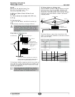
LED indications sensor R:
OSSD ON, OSSD OFF, restart interlock
(manual reset) enabling
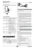
Sensor connection:
M8 x 1, 4-pole shielded female connector;
cable length 5m
Safety-monitoring module connection:
Removable screw terminal
block
Ambient temperature:
0° C ... +50° C
Storage temperature:
−10° C ... +70° C
Synchronisation:
RS 485 BUS
Protection class:
IP65 (IEC 60529)
Resistance to vibrations:
10 … 55 Hz to IEC 60068-2-6
Resistance to shock:
10 g; 16 ms; to IEC 60068-2-29
Fuses:
Power supply:
F1: 1.6 A / 250 V T
Output contacts:
F5, F6: 4.0 A / 250 V T
Signalling output:
F7: 4.0 A / 250 V T
Year of construction:
as of 2010 version 1.0
2.6 Safety classification
Standards:
EN ISO 13849-1, EN 62061
PL:
up to e
Control category:
up to 4
PFH value:
1.26 x 10
-8
/h
SIL:
up to 3
Service life:
20 years
2.7 Functions
The system consists of 2 components, the E/R sensors and the NSR-
0605 safety-monitoring module.
The connection between these components is realised through a 4-pole
female connector for the sensor connection. The transmitter and recei-
ver units are supplied with direct-current voltage through the NSR-0605
safety-monitoring module. All system components are connected to the
safety-monitoring module.
The protection field is generated between both sensors E and R, which
each represent a transmitter and a receiver unit. The safety-monitoring
module obtains the signals of the transmitter and receiver units through
a RS-485 BUS connection and makes the corresponding status
available at the output through two safety relays. To trigger a switch-off
command, covering just one light beam will suffice.
The safety light curtain is self-monitoring, i.e. for every fault occuring
in the system either during the self-test or covered by an external test,
the OSSD outputs are disabled. As long as the fault remains active, the
system will remain locked in OFF condition. This locked situation is not
cancelled by switching-off and back on the supply voltage either.
The system has the following features:
• Protective mode
• Restart interlock (manual reset)
• Contactor check
2.7.1 Protective mode / standard operation
The protective mode switches the OSSD outputs to ON state (protec-
tion field not interrupted), without external release of a switching device.
This type of protection generates an automatic restart of the machine if
the protection field is not interrupted.
This operating mode may only be chosen in conjunction with
the restart interlock (manual reset) of the machine.
This operating mode must not be chosen, when persons can
step behind the protection field.
2.7.2 Restart interlock (manual reset) / hold function
In this way, the system is kept in a locked condition after a protection
field interruption, after switch-on or after power off (OSSD's OFF state).
The locking condition will only be cancelled after the protection field is
enabled and an external command device has been actuated. To switch
between normal and hold operation (restart interlock), a slide switch on
the control unit is used.
The command devices (enabling button) must be installed
outside of the hazardous area. The operator must have a
clear view on the hazardous area when actuating the enab-
ling button.
2.7.3 Contactor control (EDM)
The contactor control monitors the controlled switching elements
(auxiliary contacts of the contactors) of both outputs. This monitoring
is realised after each interruption of the protection field and prior to
the restart (enabling) of the outputs. In this way, malfunctions of the
relays are detected, e.g. contact welding or contact spring breakage.
If the light curtain detects a malfunction of the switching elements, the
outputs are locked. (s. Electrical connection)
2.7.4 Testing / external test
The system can trigger a test cycle by means of the external test input.
By applying a signal (+ 24 VDC) at the test output, a complete self-test
is executed. The outputs change to OFF state and are re-enabled after
1.5 s if no fault is detected.
Regardless of the activation of the external test input, a self-test is
cyclically executed within the permissible triggering time of the system.
The condition at the output relays does not change. The system is only
switched off when a fault is detected.
2.7.5 Signalling output / low-voltage safety output
The safety-monitoring module has a potential-free changeover contact
for the connection of a signal lamp. In this way, the signal conditions
OSSD ON and OSSD OFF can be visualised on the machine by means
of an indicator light. The signal lamp can be operated with 12V, 24V or
42V.
3. Mounting
3.1 General conditions
The following guidelines are provided as a preventive warning notice
to ensure safe and appropriate handling. These guidelines are an
essential part of the safety instructions and therefore must always be
observed and respected.
• The SLC must not be used on machines, which can be
stopped electrically in case of emergency.
• The safety distance between the SLC and a hazardous ma-
chine movement must always be observed and respected.
• Additional mechanical safety guards must be installed so
that the operator has to pass by the protection field to reach
the hazardous machine parts.
• The SLC must be installed so that the personnel always
must be within the detection zone when operating the ma-
chine. An incorrect installation can lead to serious injuries.
• Never connect the outputs to +24VDC. If the outputs are
wired to +24VDC, they are in ON state, as a result of which
they are unable to stop a hazardous situation occuring on
the application/machine.
• The safety inspections must be conducted regularly.
• The SLC must not be exposed to inflammable or explosive
gasses.
• The connecting cables must be connected in accordance
with the installation instructions.
• The fixing screws of the end caps of the mounting angle
must be firmly tightened.

