4
EN
SLC 430
Operating instructions
Safety light curtain
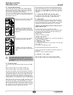
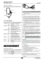
3.2 Protection field and approach
The protection field of the SLC consists of the entire range located
between the protection field markings of sensor E and R. Additional
protective devices must ensure that the operator has to pass by the
protection field to reach the hazardous machine parts.
The SLC must be installed so that personnel are always located within
the detection zone of the safety device when operating the hazardous
machine parts to be secure.
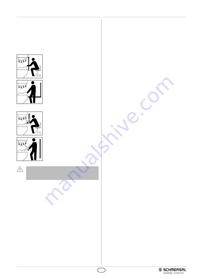
Correct installation
Hazardous machine parts can only be reached
after passing through the protection field.
The presence of staff members between the
protection field and hazardous machine parts
must be prevented/avoided (protection against
stepping over).
Unauthorised installation
Hazardous machine parts can be reached wit-
hout passing through the protection field.
The presence of staff members between the
protection field and hazardous machine parts is
enabled.
When fitting a sensor pair, please check that the E and R
sensors have identical series numbers! The sensors are
optically adjusted to each other, thus guaranteeing the max.
setting range.
3.3 Fixing of the sensors
The sensors are fitted at the required positions by means of mounting
rails.
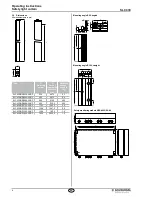
B90 mounting rail, angled (refer to chapter 3.6 Dimensions)
B180 mounting rail, straight (refer to chapter 3.6 Dimensions)
By means of two executions, various mounting types can be realised.
The angles are screwed to the base. The base must be flat and level to
avoid distortion of the sensors. The sensors must slide with the notch
at the rear of the guide slot of the mounting rail and fixed by means of
an adjusting screw. To prevent the fixing screw from loosening due to
possible vibrations, it must be secured by means of a suitable adhesive.
Please make sure that the sensors are installed correctly and not with
the, head and foot positions of both edges swapped. The connector
plugs are located at the head end of both sensors and therefore must
point in the same direction; the common direction however is not impor-
tant. The edges must be fitted at the same height, with the translucent
(light-transmissive) surfaces oriented towards each other.
One of both sensors must be turned in both directions around its lon-
gitudinal axis to determine the point for the protection field interruption
(plant switch-off). The optimal alignment is obtained when the sensors
are adjusted in the middle between both points of the protection field
interruption.
3.4 Fixation of the NSR-0605 safety-monitoring module
The safety-monitoring module can be wall-mounted by means of 4
mounting holes in its enclosure (refer to chapter Dimensions).
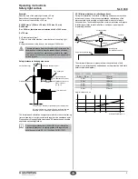
3.5 Safety distance
The safety distance is the minimum distance between the protection
field of the safety light curtain and the hazardous area. The safety dis-
tance must be observed to ensure that the hazardous area cannot be
reached before the hazardous movement has come to standstill.
Calculation of the safety distance to EN ISO 13855 (successor of
EN 999) and EN ISO 13857
The safety distance depends on the following elements:
Run-on time of the machine (calculation by run-on time measurement)
Response time of the machine and the safety light curtain and the
downstream relay (entire safety guard)
Approach speed
Resolution of the safety light curtain
Safety light curtain SLC 430
The safety distance for resolutions 14 mm up to 40 mm is calculated by
means of the following formula:
S = 2000 mm/s * T + 8 (d - 14) [mm]
S = Safety distance [mm]
T = Total reaction time (machine run-on time, reaction time of the safety
guard, relays, etc.)
d = Resolution of the safety light curtain
The approach speed is covered with a value of 2000 mm/s
If value S <= 500 mm after the calculation of the safety distance, then
use this value.
If value S >= 500 mm, recalculate the distance:
S = 1600 mm/s * T + 8 (d - 14) [mm]
If the new value S > 500 mm, use this value as safety distance.
If the new value S < 500 mm, use a minimum distance of 500 mm.

