5
EN
SLC 430
Operating instructions
Safety light curtain
Example:
Reaction time of the safety light curtain = 50 ms
Resolution of the safety light curtain = 30 mm
Run-on time of the machine = 330 ms
S = 2000 mm/s * (330 ms + 50 ms) + 8 (30 mm - 14 mm)
S = 888 mm
S = > 500 mm, therefore new calculation with V = 1600 mm/s
S = 736 mm
S = Safety distance [mm]
T = Run-on time of the m reaction time of the safety light
curtain
K = Approach speed of the body or the body part 1600 mm/s
The safety distance between the safety light curtain and the
hazardous point must always be respected and observed.
If a person reaches the hazardous point before the hazar-
dous movement has come to standstill, he/she is exposed to
serious injuries.
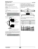
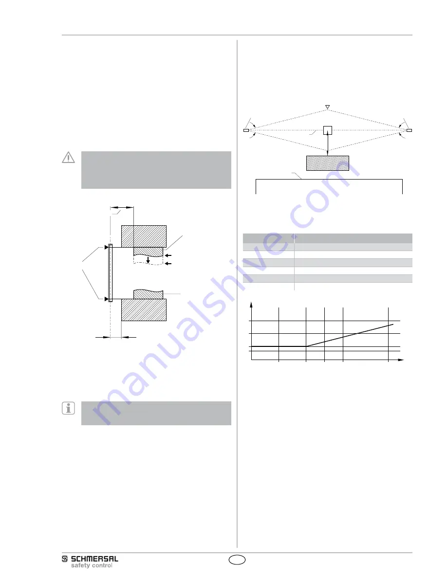
Safety distance to the dangerous area
Limit of the hazardous point
Safety distance (S)
Protection field marking
Tool - upper part
Signal to stop the
hazardous movement
Stillstand of the hazar-
dous movement
tn = tB - tA
Tool - lower part
tA
S
tB
≤ 75 mm = max. distance for protection against stepping over
To prevent persons from stepping over the protection field this
dimension must be imperatively respected and observed.
The formulae and calculation examples are related to the vertical set-up
(refer to drawing) of the light curtain with regard to the hazardous point.
Please observe the applicable harmonised EN standards and possible
applicable national regulations.
The successor standards of the EN 999 for calculating the
minimum distances of the safety guards with regard to the
hazardous point are EN ISO 13855 and EN ISO 13857.
3.5.1 Minimum distance to reflecting surfaces
During the installation, the effects of reflecting surfaces must be taken
into account. In case of an incorrect installation, interruptions of the
protection field could possibly not be detected, which could lead to
serious injuries. The hereafter-specified minimum distances with regard
to reflecting surfaces (metal walls, floors, ceilings or parts) must be
imperatively observed.
8°
8°
a= 262 mm
Access direction
Sensor R
Obstacle
optical axis
Sensor E
reflecting body
(e.g. Material container)
Limit of the hazardous point
a=105mm
5°
5°
The minimum distance a is measured from the optical axis of both
sensors to the reflecting body and depends on the protection field width
(refer to table and diagram).
SF width
Minimum distance a
0.2 m … 3.0 m
105 mm
3.5 m
123 mm
4.0 m
140 mm
4.5 m
158 mm
5.0 m
175 mm
6.0 m
210 mm
70
1,5
3,0
4,0
5,0
7,5
100
200
300
Minimum distance a in mm
Protection field width in m

