8
EN
SLC 430
Operating instructions
Safety light curtain
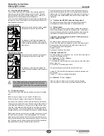
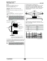
Cable screen at mounting angle
The ground connection laid together with the connecting cables must
be connected as shown to the E and R sensors through the fixation
part.
Connecting cable
KA-0610/0611
Sensor E/R
Fixing part
Earth connection
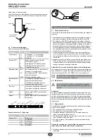
4.3 Connector configuration
Safety monitoring module NSR-0605
Description
PIN
Meaning
Power supply
V 1
V 2
Sch.
Connections 1, 2, 3 (connected)
Connections 4, 5, 6 (connected)
GROUND
Sensors E / R
+
-
B
A
Sch.
Supply voltage for sensor (brown)
0V for sensor (green)
Data signal for RS-485 bus (yellow)
Data signal for RS-485 bus (white)
Cable sheathing (black)
Signalling output AND
OR
COM
Switching signal ON - no interruption of
the beams, no system failure
Switching signal OFF - beams interrup-
ted or system failure
common switching contact
Input hold func-
tion
+
-
Connection for command device to
suppress the holding function
Connection for command device to
suppress the holding function
Test input
+
-
Input signal to trigger the system test
Input signal to trigger the system test
Output 1
1
2
Safety output OSSD 1, potential-free
NO contact
Output 2
1
2
Safety output OSSD 2, potential-free
NO contact
Power supply Output 1
Signalling output
Output 2
Sensor E Sensor RHold function
Test input
V1
V2
UND
DER
COM
Sch.
1 2
1 2
+ – B A Sch. + – B A Sch.
+ –
+ –
Connection for the E / R sensors:
Description
PIN
Color of the cable
Sensors E / R
+
BN (brown)
-
GR (green)
B
YE (yellow)
A
WH (white)
Sch.
BK (black)
+
-
B
A
Sch.
5. Set-up and maintenance
5.1 Check before start-up
Prior to start-up, the following items must be checked by the responsib-
le person.
1. Starting hazardous machine parts must be impossible as long as a
body part of a person is inside of the protection field of the BWS.
2. The actuation of the BWS (protection field interruption) during the
hazardous stage of the machine operation must cause the hazardous
parts to be stopped or, where appropriate, to change to a different
safe state before they can be reached by a body part of a person. It
must be impossible to restart the hazardous parts before the BWS
has completely returned to its normal state and the machine control
elements have been reactuated.
3. Check the machine to ensure that there are no other mechanical
or structural aspects preventing the machine from being stopped or
from switching to a different, safe state through a switching command
of the BWS.
4. Examine and check the machine control and the connections to the
BWS to make sure that no changes have been made, which have
a negative impact on the system and that suitable and appropriate
changes have been adequately registered.
Switch the SLC on and check the operation in the following way:
The component performs a system test after the operating voltage has
been switched on. After that, the outputs are enabled (if the protection
field is not interrupted). The LED "OSSD ON" of the receiver is on.
In case of incorrect functioning, please follow the instructions
listed in the chapter Fault diagnostic.
5.2 Maintenance
Do not use the SLC before the next inspection is termina-
ted. An incorrect inspection can lead to serious and mortal
injuries.
Conditions
For safety reasons, all inspection results must be archived. The ope-
rating principle of the SLC and the machine must be known in order to
be able conducting an inspection. If the fitter, the planning technician
and the operator are different persons, please make sure that the user
has the necessary information at his disposal to be able conducting the
maintenance.
5.3 Regular check
A regular visual inspection and functional test, including the following
steps, is recommended:
1. The component does not have any visible damages.
2. The optics cover is not scratched or soiled.
3. Hazardous machinery parts can only be accessed by passing
through the protection field of the SLC.
4. The staff remains within the detection area, when works are conduc-
ted on hazardous machinery parts.
5. The safety distance of the application exceed the mathematically
calculated one.
Operate the machine and check whether the hazardous movement
stops under the hereafter-mentioned circumstances.
6. Hazardous machine parts do not move when the protection field is
interrupted.

