9
EN
SLC 430
Operating instructions
Safety light curtain
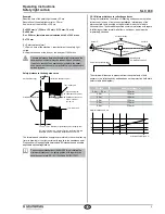
7. The hazardous machine movement is immediately stopped, when
the protection field is interrupted with the test rod immediately before
the sensor E, immediately before the sensor R and in the middle
between the sensor E and R.
8. No hazardous machine movement when the test rod is within the
protection field.
9. Gefährliche Maschinenbewegung kommt zum Stillstand, wenn die
Spannungsversorgung des SLC ausgeschaltet wird.
5.4 Half-yearly inspection
The following items must be checked every six months or when a ma-
chine setting is changed.
1. Machine stops or does not inhibit any safety function.
2. No machine modification or connection change, which affects the
safety system, has taken place.
3. The outputs of the SLC are correctly connected to the machine.
4. The total response time of the machine does not exceed the respon-
se time calculated during the first putting into operation.
5. The cables, the connectors, the caps and the mounting angles are in
perfect condition.
5.5 Cleaning
If the optics cover of the sensors is extremely soiled, the OSSD outputs
can be disabled. Clean with a clean, soft cloth with exercising pressure.
The use of agressive, abrasive or scratching cleaning agents,
which could attack the surface, is prohibited.
6. Diagnostic
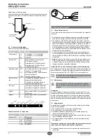
6.1 LED status information
GN
YE
RD
Sensor R
Function
LED
Description
Restart interlock
(manual reset)
yellow Signal request by external com-
mand device (pushbutton)
OSSD OFF
red
Safety outputs OFF state
OSSD ON
green
Safety outputs ON state
OR
Sensor E
Function
LED
Description
Transmitter ON orange Sensor E active
6.2 Optical and acoustic signals in the control unit
The control unit includes an acoustic signal generator (buzzer) as well
as multiple LED's.
The LED's n° 1, 2 and 3 (green) are permanently on when the operating
voltage is present. The LED's 4 and 6 (yellow) and the LED's 5 and
7 (red) show the respective system condition. The acoustic signal is
activated or deactivated by means of the buzzer switch.
The following tables show the different indication types for the system
conditions. The acoustic signal however is only emitted, when the
buzzer is switched on.
NSR-0605
2
1
3
5
4
6
7
F1
F5
F6
F7
H
N
ON
H - Hold function
N - Normal function
Service
fuse
Buzzer switch
Function switch
Buzzer
OFF
6.2.1 Protective mode / standard operation
Status of the protection field
no interruption
continuous interruption
red LED's
(5; 7)
flashing
flashing
yellow
LED‘s (4; 6)
continuously on
off
acoustic
signal
none
short interval
6.2.2 Mode of operation restart interlock (manual reset) / hold
function
A) Everytime the operating voltage is switched on
Start interlock active
red LED's
(5; 7)
continuously on
yellow
LED‘s (4; 6)
off
acoustic
signal
constant
The system waits for the command device to be actua-
ted. For the system condition OSSD's ON, the protection
field must be permanently clear after the actuation of the
command device (hold function input) for 300 ms. If the pro-
tection field is clear (no IR beam interrupted), the system is
enabled. If not, the LED's 4, 6 (yellow) will be off, the LED"s
5, 7 (red) will be permanently on and a constant acoustic
signal is emitted.
B) In operation
Status of the protection field
no interruption
continuous or previous inter-
ruption
red LED's
(5; 7)
flashing
continuously on
yellow
LED‘s (4; 6)
continuously on
off
acoustic
signal
none
constant

