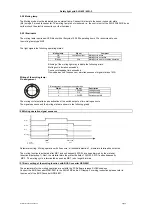
5.5.1 Muting sensors MS
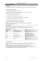
The muting sensor MS can be a mechanic, capacative, inductive or opto-electronic sensor.
There is no specific requirement concerning error protection. The arrangement must be secured against
manipulation. If reflexion light barriers are used we recommend to install sensors and reflectors in
to use a dark-switched type. (sensor dimmed = output 24 V/DC)
entire length without interruptions. The sensors must detect the material, not the means of transportation.
Make sure that the sensor distance is not too large, so that all activated muting sensors are dimmed
by the passing material during a cycle. Simultaneousness (max. 3 sec) of the switch outputs must
be taken into consideration.
A new muting procedure can start as soon as the previous process is finished (sensors not dimmed).
A safety distance of at least 50 mm (conveyor speed V < 2.0 m/s) to the protective field is required
to ensure proper signal evaluation by the control unit.
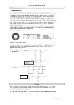
Pin assignment of the sensors
PIN assignment in the sensor connector box
PIN Nr
Signal
Description
1
+ 24V/DC
3
OV
4
+ 24V/DC
Installation of the muting sensors
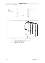
If 4 muting sensors are used the outputs of the sensors MS1 and MS3 and MS2 and MS4 must be
connected in parallel. MS1 and MS3 are connected to the sensor connector plate at input MS1.
Connect MS4 and MS2 to input MS2.
Connection of the sensors
- 2 muting sensors
- 4 muting sensors
When arranging the muting sensors make sure that unintentional intrusion of a person into the danger
zone is not possible. The distance and the height of the muting sensors must be appropriate for clear
differentiation between material and person.
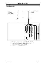
The wiring layout of the muting sensors to the AOPD must exclude cross circuiting due to defect cables.
Page 8
Subject to technical changes
Voltage supply
Voltage supply
Safety light grid SLG 422/ 425I-P
alternating order to avoid mutual interference. If you use opto-electronic sensors please make sure
The sensors must be arranged in a way that the transported piece of material is detected over the
Switch output of sensor
Attention!
5.5 External components
4
1
3
4
1
3
M S 2
A LFA 4
s ensor connection
MS 1
+ 24V / DC
M S 1
M S 2
MS 2
AL FA 4
se nsor conn ection
MS 1
+ 24V / DC
MS 1
MS 3
M S 2
MS 4
SLG 425IP
Sensor connection
SLG 425IP
Sensor connection

