background image

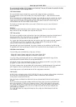
When you have properly connected the muting application and the NSR-0801, select the following parameter 
settings according to your intended application in the menu option Muting Function of your PC software.

First please select the operating mode and the transport direction with the mouse pointer (arrangement and 
number of muting sensors).

 - Muting with 2 sensors, diagonal arrangement

Muting mit 2 diagonally mounted muting sensors
Transport direction: Material transport in two directions (default) 
Selectable options: Conveyor stop, muting cycle shortened, override, protective field range

 - Muting with 2 sensors, parallel arrangement

Muting  with 2 muting sensors; 

Attention!

 Do not mount the muting sensors outside of 

the danger zone!
Transport direction: out of the danger zone, muting cycle shortened (default). 
Selectable options: Conveyor stop,  override, protective field range

 - Muting with 4 sensors, parallel arrangement

Muting with 2 muting sensors each, symmetrical arrangement in front of and after the 
protective field of the SLG 420. 
Transport direction: Material transport selectable in both directions
Selectable options: Conveyor stop, muting cycle shortened, override, protective field range

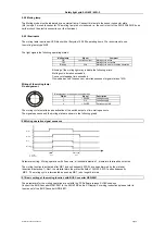
5.9.1 Muting cycle duration

The muting cycle duration is the time between activation and termination of the material tansport into or out of the 
danger zone.
The muting cycle duration depends on the length of the material, the conveyor speed and the arrangement 
of the sensors. The duration setting must comprise one complete muting cycle (release of all sensors). A new
muting cycle can only be started when all sensors are released (no dimming).

The muting cycle duration can be set between a few second and many hours. Longer muting cycle durations 
can be generate a dangerous operating situation.
Consider variations of conveyor speed, position and length of the material when setting the muting 
cycle duration.

5.9.2 Simultaneouness of the sensors

The time range between the 1st and the 2nd muting sensor is monitored. Thus a symmetrically shaped body  
can be differentiated clearly from other time ranges (intrusion of a person) by an appropriate arrangement 
of the muting sensors.
The simultaneouness setting should take variations of the conveyor speed, position and length of the 
material into consideration.

Simultaneouness of the sensors can be set between 1 and 3 seconds. 

Page 10

Subject to technical changes

5.9 Operating mode and transport direction

5.8 Setting for muting operation

Safety light grid SLG 422/ 425I-P

Summary of Contents for SLG 422

Page 1: ...Safety Light Grid SLG 422 425I P Operating Manual Reflection mirror ULS P 0501 ...

Page 2: ...th BUS Converter NSR 0801 09 5 8 Setting for muting operation 10 5 9 Operating mode and transport direction 10 5 9 1 Muting cycle duration 10 5 9 2 Simultaneousness of the sensors 10 5 9 3 Restart interlock 11 5 9 4 Conveyor stop 11 5 9 5 Muting cycle shortened 11 5 9 6 Override 11 5 9 7 Multiple break of protective field during muting cycle 12 5 10 Storage of information 12 5 11 Muting applicatio...

Page 3: ...ies included in the delivery package 24 9 2 Optional accessories 24 10 Safety Instructions 25 10 1 Inspection according to machine maintenance 25 10 2 Inspection every six months 25 10 3 Cleaning 25 11 Contact 26 12 Annex 27 Inhalt ...

Page 4: ...G 422 425I P on machines that cannot be stopped by electrical emergency shut down The safety distance between SLG 422 425I P and hazardous machine movements must be maintained at all times s chapter 4 1 Installation requirements Additional mechanical safety precautions are to be installed in a way that dangerous machine parts can not be reached without passing through the detection zone s chapter ...

Page 5: ...rter NSR 0801 and a PC Laptop see manual NSR 0801 3 3 1 1 Automatic mode Automatic start after release of detection zone The Automatic mode function switches the OSSD outputs ON detection zone not interrupted without external release of a switching device This mode of operation must be selected in combination with the restart interlock of the machine This degree of protection initiates an automati...

Page 6: ...he outputs at the receiver will not switch ON The OSSD OFF LED will flash to signal an error message For further information please refer to chapter 7 2 Error diagnosis Permanent self test In the background the system checks all safety functions within the cycle time This time includes a check of all functional components and a complete memory test 3 4 Diagnosis Window Function LED colour Multi fu...

Page 7: ... movement has stopped The following equations and calculation examples refer to vertical adjustment of the safety light curtain to the danger spot Calculation of the safety distance according to EN 999 and EN 294 The following factors are decisive when determining the safety distance Machine after running time determined by measuring the after running time Response time of machine and safety light...

Page 8: ...ver reference level floor in mm 400 900 Attention Safety light grid SLG 422 425I P danger spot before the dangerous movement has stopped might get seriously injured Always keep the safety distance between the SLG 422 425I P and the danger spot Any person that can reach the installation might result in improper detection of detection zone interruptions and thus lead to serious injuries When install...

Page 9: ... surfaces at an effective aperture angle of 5 0 to take misalignment during installation into account See following table Distance m between Minimum distance a SLG and ULS mm 0 2 bis 3 0 262 4 350 5 437 6 525 Formula a tan 2 5 x L mm a Minimum distance to reflective surfaces L distance between SLG 422 425I P and mirror ULS Page 6 Subject to technical changes Safety light grid SLG 422 425I P a mm D...

Page 10: ...ed depending on the intended use The connection and the assembly of all components must be realised by specialists who are trained in electronics and who know the appropriate safety regulations Testing and initiation by competent experienced people who have the required specialised knowledge especially of all pertinent legal and official regulations Introduction and training by a specialist for th...

Page 11: ...Description 1 24V DC 3 OV 4 24V DC Installation of the muting sensors If 4 muting sensors are used the outputs of the sensors MS1 and MS3 and MS2 and MS4 must be connected in parallel MS1 and MS3 are connected to the sensor connector plate at input MS1 Connect MS4 and MS2 to input MS2 Connection of the sensors 2 muting sensors 4 muting sensors When arranging the muting sensors make sure that unint...

Page 12: ... switch outputs of two muting sensors The signal sequence and the muting state are shown in the following graph Parameter setting Muting operation with 2 sensors directional detection 1 premature termination not active The muting function is activated after MS 1 and subsequently MS 2 have been dimmed by the material directional detection 1 Next the material dims the protective field of SLG 420 MS ...

Page 13: ...ed override protective field range 5 9 1 Muting cycle duration The muting cycle duration is the time between activation and termination of the material tansport into or out of the danger zone The muting cycle duration depends on the length of the material the conveyor speed and the arrangement of the sensors The duration setting must comprise one complete muting cycle release of all sensors A new ...

Page 14: ...y long muting cycle duration the conveyor stop time can be prolonged by max 18 hours 5 9 5 Muting cycle shortened A normal muting cycle is terminated by a muting sensor as follows Muting with 2 sensors diagonal arrangement after release of sensor MS 2 Muting with 4 sensors parallel arrangement after release of sensor MS 3 A very long muting cycle duration produces a time window with bridged protec...

Page 15: ...re prepared for storage by activating the button To prevent unintentional storage of the information every intended storage processs must be confirmed by clicking an additional button within 10 seconds If you click this button within the given period the new configuration will be transmitted to the safety light grid SLG 425I P If you fail to press the button within the requested time the informati...

Page 16: ...sported material to prevent gaps Otherwise there is a risk of people getting between material and arrangement of the MS during the muting cycle If you work with different material dimensions width make sure to protect the gap between the sensors emitter receiver with an additional cover Muting with 2 sensors parallel arrangement The arrangement shows the muting application with two parallel sensor...

Page 17: ... Default setting Material transport in both directions Arrange the muting sensors in a way that a unique sequencing of the sensors is ensured The intersection of the two muting sensors should always be within the danger zone Muting with 4 sensors parallel arrangement The arrangement shows the muting application with four sensors in parallel This arrangement enables the Material transport in both d...

Page 18: ... DC 0 V DC Nur für Diagnose DIAG IN DIAG OUT Freigabe WA Schützkontrolle EDM 24 V DC 0 V DC OSSD 1 OSSD 2 K1 K2 Brücke 2 Brücke 1 Kn1 Kn2 S 1 Erdung E1 2 4 1 3 1 8 2 7 3 4 6 5 DIAG IN DIAG OUT 24V 0V Nur für Diagnose DIAG IN DIAG OUT Freigabe WA Schützkontrolle EDM 24V 0V OSSD 1 OSSD 2 K1 K2 Brücke 2 Brücke 1 Kn 1 Kn 2 Erdung E1 2 4 1 3 1 8 2 7 3 4 6 5 DIAG IN DIAG OUT 24 V DC 0 V DC Nur für Diagn...

Page 19: ...24 V DC 0 V DC OSSD 1 OSSD 2 K1 K2 Brücke 2 Brücke 1 Kn1 Kn2 S 1 Erdung E1 2 4 1 3 1 8 2 7 3 4 6 5 DIAG IN DIAG OUT 24V 0V Nur für Diagnose DIAG IN DIAG OUT Freigabe WA Schützkontrolle EDM 24V 0V OSSD 1 OSSD 2 K1 K2 Brücke 2 Brücke 1 Kn 1 Kn 2 Erdung E1 2 4 1 3 1 8 2 7 3 4 6 5 DIAG IN DIAG OUT 24 V DC 0 V DC Nur für Diagnose DIAG IN DIAG OUT Freigabe WA Schützkontrolle EDM 24 V DC 0 V DC OSSD 1 OS...

Page 20: ...inst overload The power supply fulfills the regulations of the EEC industrial environment The power supply fulfills the low voltage directive The grounded conductor of the power supply unit should be connected to a grounding point PE The voltage levels must be within the limits 24VDC 10 Subject to technical changes Page 17 Safety light grid SLG 422 425I P Diagnosis OUT Power supply 6 3 Connection ...

Page 21: ... 7 3 Diagnostic operation This mode of operation is automatically activated after Power Reset if the BUS Converter NSR 0801 is connected to the receiver or transmitter How to connect the BUS converter is described in the NSR 0801 operating manual When diagnostic operation is active the OSSD ON and OSSD OFF LEDs of the receiver flash In diagnostic operation Normal Mode function is not possible Ther...

Page 22: ...e High Turn on voltage Low Switching current Stray current Load capacity Load inductive reactance Start restart interlock relay monitoring EMD Permittable output resistance between OSSD and load Feed line Low level input voltage inactive Low level input current High level input voltage inactive Low level input voltage active Low level input current Safety light grid SLG 422 425I P Type SLG 422 P 0...

Page 23: ... L2 1 SLG 422P E R0500 02 RF 500 681 316 303 Page 20 Subject to technical changes L2 Mounting distance mm between floor and centre long hole diagnosis window C Total length 1 L1 Mounting distance mm between floor and centre long hole short end cap Safety light grid SLG 422 425I P 717 86 L1 L2 A C B 80 97 6 05 48 7 49 6 84 31 5 42 ...

Page 24: ...P E R0500 02 RF 500 745 316 239 Subject to technical changes Page 21 L1 Mounting distance mm between floor and centre long hole short end cap L2 Mounting distance mm between floor and centre long hole diagnosis window C Total length 1 Safety light grid SLG 422 425I P 781 150 L1 L2 A C B 80 161 6 05 48 7 49 6 84 31 5 42 ...

Page 25: ... 606 648 690 All data in mm tolerance 1 0 mm 8 3 Mounting accessories 8 3 1 Mounting set MS 1030 The mounting bracket is composed of 4 steel angles and 16 fastening screws Page 22 Subject to technical changes Safety light grid SLG 422 425I P 40 52 32 20 6 5 42 14 5 18 9 40 52 32 20 6 5 42 14 5 18 9 ...

Page 26: ... beams protective height in mm E Emitter R Receiver unit SLG 422 425IP Safety Light Grid Subject to technical changes Page 23 Safety light grid SLG 422 425I P 10 15 Following table shows the response time of the safety light grid SLG 422 425I P Middle mounting is an alternative fastening method at the side of the profile A combination of the middle mounting brackets is recommendable for higher mec...

Page 27: ...rs stability for industrial applications A mounting set includes to the delivery BUS Converter NSR 0801 Converter for parametrization and diagnosis For detailed information please refer to the operating manual of NSR 0801 Delivery package Extension cable integrated PC LxWxH 122 x 60 x 35mm measured without cables Page 24 Subject to technical changes Software and USB 2 0 connection Description M12 ...

Page 28: ...les and plugs of SLG 422 425 IP are in flawless condition 6 The brackets end caps and cables are secured tightly 10 3 Cleaning If the optical cover of the sensors is extremely dirty the outputs OSSD of SLG 422 425 IP may be switched off Clean it with a clean soft cloth without applying pressure Do not use aggressive scouring or scratching detergents which might attack the surface 11 Contact Suppor...

Page 29: ...enter issued an EU examination certificate Mühldorf 19 12 2008 Christian Spranger Klaus Schuster Geschäftsführer Manager In agreement with the EEC guideline 89 336 EWG the CE marking will be attached This explanation certifies the agreement with the guidelines mentioned but contains no warranty of characteristics The provided product documentation safety references has to be considered absolutely ...

Reviews: