7 Testing and Initiation
7.1 Check list
Prior to initiation of SLG 422/425I-P all of the following check list items have to be verified by the responsible person.
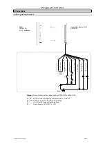
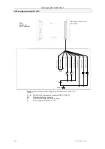
Check the wiring before the initiation:
1. The power supply is only connected to SLG 422/ 425 IP .
2. The power supply unit is a 24V/DC power supply unit fulfilling the regulations of the EEC, the Low
Voltage Directive and the product standard (IEC 61496).
3. The polarity of the power supply is not reversed.
4. The connection cable is properly connected to the transreceiver.
5. The double insulation is provided between the light grid output and a hazard potential.
6. The outputs OSSD1 and OSSD2 are not shorted to +24 V/DC.
7. The connected switch elements (load) are not shorted to 24V/DC.
Switch the SLG 422/ 425 IP on and test its functionality as follows:
2 seconds after power ON (when the detection zone is unobstructed) the system starts to operate
properly. The outputs are released.
7.2 Troubleshooting
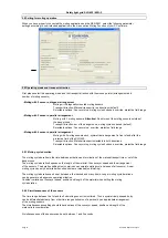
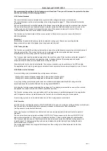
After power ON and release of the detection zone the light grid runs an internal self test. If an error
occurs, the OSSD OUT (red) LED of the receiver flashes in a special flicker pattern. Every error message is
followed by a interval of one second.
LED OSSD OFF
Continual flash OSSD OFF and
LED Restart
1 x flash
2 x flash
3 x flash
4 x flash
5 x flash
6 x flash
7.3 Diagnostic operation
This mode of operation is automatically activated after Power Reset, if the BUS Converter NSR-0801 is
connected to the receiver or transmitter. How to connect the BUS converter is described in the NSR-0801 operating
manual.
When diagnostic operation is active, the OSSD ON and OSSD OFF LEDs of the receiver flash.
In diagnostic operation Normal Mode function is not possible. Therefore the output OSSDs are interlocked.
The system will automatically switch from diagnostic operation to normal mode function as soon as the BUS converter
is no longer integrated and the extension cord of the sensor is connected again.
Page 18
Subject to technical changes
Error
Error configuration data
interruption, i.e. interlock.
Error on the output OSSDs
After correction do a power reset
short circuit aUB and mass.
Check output connections; check OSSD for
(Restart interlock, automatic operation)
Error Relay control ON
Check wiring of auxiliary contacts
Error on the sensor of the receiver
Connections
Error on Relay control OFF
Exchange receiver
Check connection on input Relay control, see
NSR 801
Check configuration defaults with the BUS converter
Check connection of receiver, wiring 1 or
Improper wiring
NSR 801
Remedy
wiring 2 must be wired up properly (s. Connections).
Check short circuit aUB and mass
Check connection on input Relay control for
Check configuration defaults with the BUS converter
Safety light grid SLG 422/ 425I-P
Error blanking
Receiver detects blanked beams as beams without


