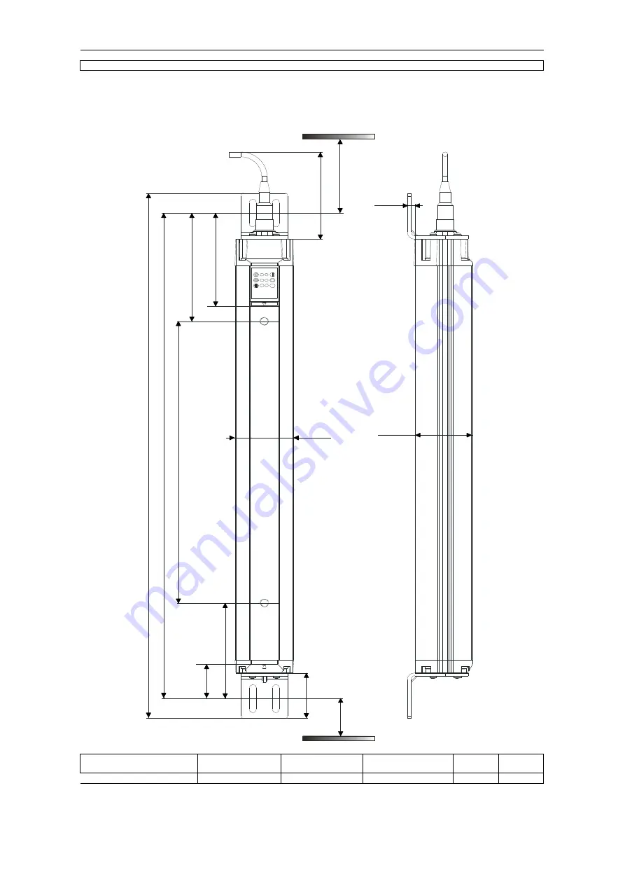
8.2 Dimensioned drawings
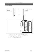
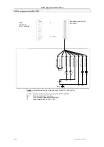
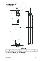
8.2.1 Dimensioned drawings standard
SLG422P-E/R0500-02-RF
Type
A
beam distance ± 1
B
Mounting dimens. ± 1
L1
± 1
L2
± 1
SLG 422P-E/R0500-02-RF
500
681
316
303
Page 20
Subject to technical changes
L2 = Mounting distance (mm) between floor and centre long hole (diagnosis window)
C
Total length ± 1
L1 = Mounting distance (mm) between floor and centre long hole (short end cap)
Safety light grid SLG 422/ 425I-P
717
8
6
L
1
L
2
A
C
B
8
0
9
7
6,05
48,7
49,6
8
4
3
1
,5
4
2

