10
Operating instructions
Safety light grids
SLG440
EN
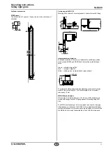
3.6 Dimensions transmitter and receiver
All measurements in mm
75
70,8
A
B
C
22,2
24
7,7
33
27,8
L2
L1
41,5
82,5
Type
A
Beam
distance
B
Mounting
dimen-
sion
C
Total
lenght
L1
L2
SLG440-ER-0500-02-XX
500
624
643
3585
3175
SLG440-ER-0800-03-XX
400
924
943
2585
2175
SLG440-ER-0900-04-XX
300
1024
1043
2585
2175
L1 = Mounting distance (mm) between floor and slotted hole centre
(short end cap)
L2 = Mounting distance (mm) between floor and slotted hole centre
(diagnostic window)
Overall length Ls (dimension end cap with regard to the
cable connection up to the connector M12) of the sensors
SLG440-ER-0500-02-XX
610 mm
SLG440-ER-0800-03-XX
910 mm
SLG440-ER-0900-04-XX
1010 mm
3.7 Fixing
Included in delivery
Mounting kit MS-1100
The mounting kit consists of 4 steel angles and 8 fixing screws
5,5
17
28
24
7
11
24
38

