6
Operating instructions
Safety light grids
SLG440
EN
Transmitter parameter setting
Wiring of the transmitter
- Jumper connection
pin 1 with pin 2
- Jumper connection
pin 3 with pin 4
Pin 1
Pin 2
+ 24V/DC
Pin 3
Pin 4
0V/DC
The response time of the system is increased when beam
coding A is used To this end, the safety distance must be
adjusted Refer to chapter: Response time
2.11 Parameter setting
The parameter setting of the SLG440 enables the individual adjustment
of the desired functionality to the application
Parameter display (7-segment display)
A = parameter active
- = parameter not active
S.
= save the current configuration
C.
= delete the current configuration, new configuration = factory setting
n = unavailable (unauthorised setting, refer to Parameter setting infor-
mation)
d.
= diagnostic/setting mode
Parameter selection
Selection, change and acceptance of the parameters by means of the
command device pushbutton S1:
- Switch to parameter setting Px briefly press the button
01 … 15 sec
- Change parameter setting Px
press button 25 … 6 sec
- Save
S.
/ Factory setting
C.
press button 25 … 6 sec
Procedure
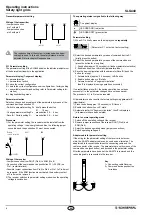
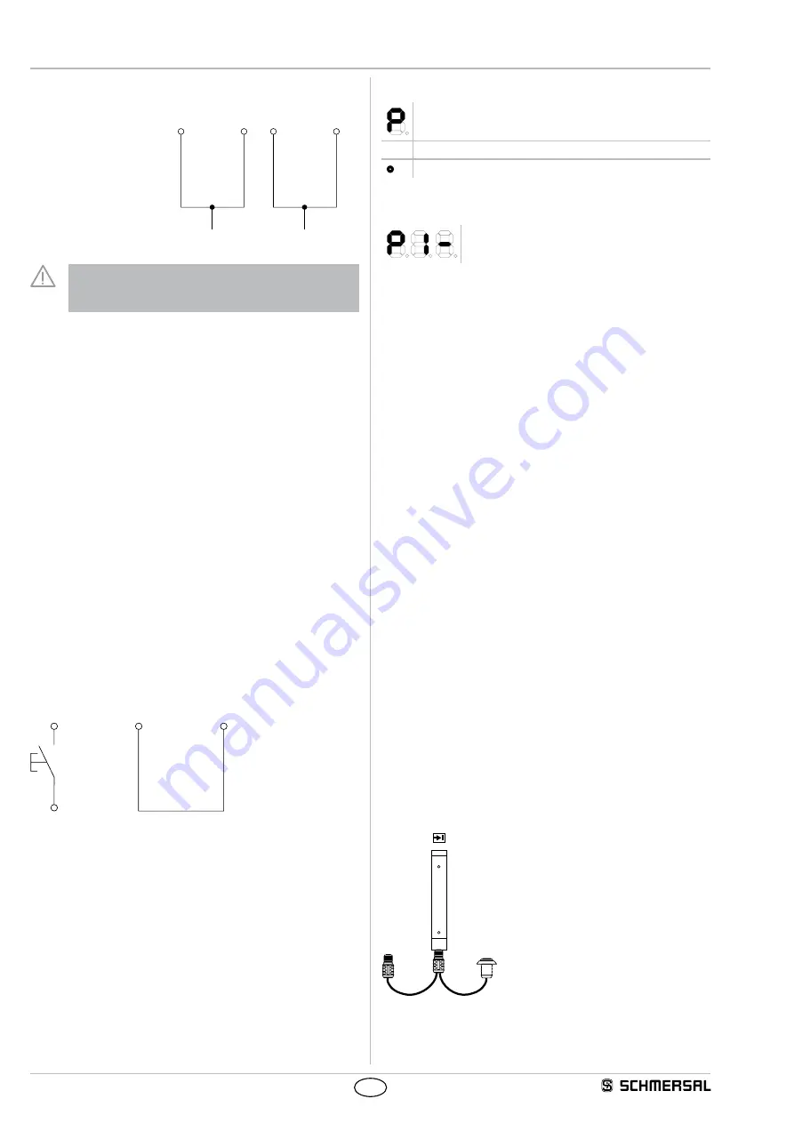
1) For the parameter setting, the receiver must be isolated from the
operating voltage In de-energised condition, the following jumper
connection and the pushbutton S1 must be connected
Freigabe WA
DOUT
EDM
Pin 8
Pin 6
Pin 1
S 1
+ 24 VDC
Release
restart interlock
Wiring of the receiver
• Jumper connection from DOUT (Pin 6) to EDM (Pin 8)
• Connection of the command device pushbutton S1 (+24 VDC) on
Pin 1 (restart interlock)
• Possible jumper connections from Pin 5 to Pin 6 or Pin 1 to Pin 6 must
be removed If the EDM function was activated, the auxiliary contact
of Pin 8 must be removed
2) The receiver switches to parameter setting mode when the operating
voltage is switched on
The operating status is signalled in the following way
7- segment display
●
LED OSSD ON (red) active
●
LED OSSD OFF (green) active
Parameter setting
1) When S1 is briely pressed, the display shows
repeatedly
- (Parameter P 1 not active, factory setting)
2) Select the desired parameter by means of command device S1
(briefly press the button)
3) Select the desired parameter by means of the command device
(press the button for a long time)
1 Push button (approx 25 seconds)
➔
-
flashes (parameter not active)
2 Enable button when
➔
A
static (parameter active)
4) Save the new configuration with the parameter Save
S.
(push the
button for a long)
1 Actuate button (approx 25 seconds)
➔
S.
lashes
2 Enable button when
➔
S.
static
3 Automatic restart
➔
"segment circulation"
then
P
is displayed (saving operation successful)
If no restart takes place (
S.
), the saving operation has not been
successful (ie the parameter changes have not been saved)
The procedure 4 (1 to 3) must be repeated
All parameters can be reset to the factory setting using parameter
C.
(clear/delete)
1) Press the button approx 25 seconds)
➔
C.
flashes
2) Enable the button when
➔
C.
static
3) Automatic restart
➔
"Segment circulation", then
P
is displayed
(all parameters have been deleted)
Return to normal operating mode
1 Switch off the operating voltage at the receiver
2. Remove jumper connection at the receiver DOUT (Pin 6) and
EDM (Pin 8)
3 Select the desired operating mode (jumper connections)
4 Switch operating voltage on
Adapter cable for parameter setting
If the wiring for the parameter setting of the receiver is not acces-
sible, the KA-0974 adapter cable can be used as an alternative The
adapter cable is connected between the connecting cable and the
cable connector of the receive The parameters are set by means of the
command device (pushbutton), as described in the parameter setting
After the parameters have been set, the KA-0974 is removed and the
connecting cable is connected to the receiver
1
2
Key
1 = Connecting cable Receiver
2 = Command device pushbutton
for release

