background image

13

SLG440

Operating instructions
Safety light grids

EN

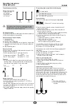
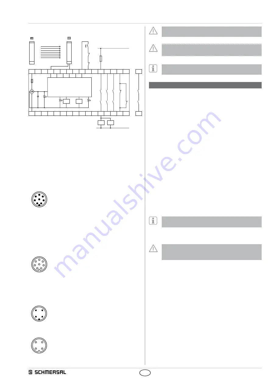
4.2  Wiring example SLG440

A2

A1

S12 S11 S21 S22

X1 X2

13

L1

33 41

23

K2

K1

Ui

K2

K1

F1

Ansteuerlogik/
Logic

14 24 34 42

N

S

J

K

A

K

B

K

A

K

B

K

B

K

A

Safety monitoring module SRB 301 MC

•  Contactor control K

a

 and K

b

 at X1/X2

•  Command device 

J

 Restart interlock restart at X1/X2

•  OSSD outputs at S12 and S22 

•  QS-switch = nQS, deactivate cross-wire short detection

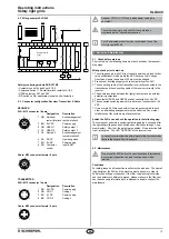
4.3  Connector configuration Receiver, Transmitter & Cable

RECEIVER

SLG: M12 connector / 8 pole

Designation

Description

5

8

4

3

2

1

7

6

1 WH Release/ 

restart interlock

Acknowledgement  

restart interlock

2 BN

24 VDC

Power supply

3 GN

OSSD 1

Safety output 1

4 YE

OSSD 2

Safety output 2

5 GY

Restart 2

Acknowledgement  

restart interlock 2

6 PK

DOUT

Operating mode

7

BU

0 VDC

Power supply

8 RD

Contactor 

control

Input EDM

Cable: M12 connector female / 8 pole

5

8

4

3

2

1

7

6

TRANSMITTER

SLG: M12 connector / 4 pole

Designation

Description

3

2

1

4

1 BN

24 VDC

Power supply

2 WH COD 1

Coding 1

3

BU

0 VDC

Power supply

4 BK

COD 2

Coding 2

Cable: M12 connector female / 4 pole

3

2

1

4

Connect COD 1 / COD 2 only when beam coding A is 
activated!

The colour codes are only valid for the cable types  
mentioned below "optional accessories"

For UL evaluated products we do recommend to use the 


UL style cable 20549.

5.  Set-up and maintenance

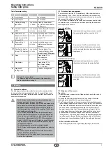
5.1  Check before start-up

Prior to start-up, the following items must be checked by the responsi-
ble person

Wiring check prior to start-up

1  The voltage supply is a 24V direct current power supply (see techni-

cal specifications), which meets the CE Directives, Low Voltage 
Directives A power downtime of 20 ms must be bridged

2  Presence of a voltage supply with correct polarity at the SLG
3  The connecting cable of the transmitter is correctly connected to the 

transmitter and the connecting cable of the receiver correctly to the 
receiver

4  The double insulation between the light grid output and an external 

potential is guaranteed

5  The outputs OSSD1 and OSSD2 are not connected to +24 VDC
6  The connected switching elements (load) are not connected to +24 

VDC

7  If two or more SLG are used within close range compared to each 

other, an alternating arrangement must be observed Any mutual 
interference of the systems must be prevented

Switch the SLG on and check the operation in the following way:

The component performs a system test during approx 2 seconds after 
the operating voltage has been switched on (indication through 7-seg-
ment display)  After that, the outputs are enabled, if the protection field 
is not interrupted  The LED "OSSD ON" at the receiver is on

In case of incorrect functionality, please follow the instructions 
listed in the chapter Fault diagnostic

5.2  Maintenance

Do not use the SLG before the next inspection is terminated  
An incorrect inspection can lead to serious and mortal 
 injuries

Conditions

For safety reasons, all inspection results must be archived  The operat-
ing principle of the SLG and the machine must be known in order to 
be able conducting an inspection If the fitter, the planning technician 
and the operator are different persons, please make sure that the user 
has the necessary information at his disposal to be able conduct the 
maintenance

Summary of Contents for SLG440

Page 1: ...About this document 1 1 Function 1 1 2 Target group authorised qualiied personnel 1 1 3 Explanation of the symbols used 1 1 4 Appropriate use 2 1 5 General safety instructions 2 1 6 Warning about mis...

Page 2: ...liability for damages and malfunctions resulting from defective mounting or failure to comply with this operating instructions manual The manufacturer shall accept no liability for damages result ing...

Page 3: ...restart interlock restart interlock 2 Input voltage HIGH active 11 30 V Input voltage LOW inactive 0 2 0 V Input current HIGH 3 10 mA Input current LOW 0 3 mA Functions automatic mode restart interloc...

Page 4: ...tputs OSSD s ON state after switch on of the operating volt age or an interruption of the protection field The system switches the outputs only to ON state when an external command device restart butt...

Page 5: ...is required The contactor control is not activated upon delivery The function is activated in parameter setting mode P 4 Connection EDM Wiring of the receiver Kn1 Kn2 auxiliary contact of the last sw...

Page 6: ...signalled in the following way 7 segment display LED OSSD ON red active LED OSSD OFF green active Parameter setting 1 When S1 is briely pressed the display shows repeatedly Parameter P 1 not active f...

Page 7: ...lication machine The safety inspections must be conducted regularly The SLG must not be exposed to inflammable or explosive gasses The connecting cables must be connected in accordance with the instal...

Page 8: ...eceive signal OK Beam b no receive signal Beam a and beam b receive signals OK Indication basic setting The signal strength is displayed per beam with two segments for the first a and the last b beam...

Page 9: ...tion from which the hazardous area is accessed To calculate the minimum distances of the safety guards with regards to the hazardous point the EN ISO 13855 and EN ISO 13857 must be observed If an over...

Page 10: ...0900 04 XX 300 1024 1043 258 5 217 5 L1 Mounting distance mm between floor and slotted hole centre short end cap L2 Mounting distance mm between floor and slotted hole centre diagnostic window Overal...

Page 11: ...reen outputs H signal 24V Red outputs L signal 0V Yellow setting mode restart interlock manual reset 24 5 12 5 15 0 1 The integrated status indication does not change the mounting dimen sion B or the...

Page 12: ...N 0 VDC BU Earth connection Restart interlock manual reset bridge 1 By bridging restart 2 pin 5 and DOUT pin 6 the restart interlock manual reset is activated Connect S1 to Pin1 Protective mode Automa...

Page 13: ...power supply see techni cal specifications which meets the CE Directives Low Voltage Directives A power downtime of 20 ms must be bridged 2 Presence of a voltage supply with correct polarity at the S...

Page 14: ...ring the first putting into operation 5 The cables the connectors the caps and the mounting angles are in perfect condition 5 5 Cleaning If the optics cover of the sensors is extremely soiled the OSSD...

Page 15: ...blanking area s of fixed or floating objects with the selected parameter setting fault elimination repeat configuration in the parameter setting possibly adjust P 1 P 2 P 3 Configuration error in para...

Page 16: ...13144608 Person authorized for the compilation of the technical documentation Oliver Wacker M ddinghofe 30 42279 Wuppertal K A Schmersal GmbH Co KG M ddinghofe 30 D 42279 Wuppertal Postfach 24 02 63...

Reviews: