background image

4

Operating instructions

Safety-monitoring module

SRB 202CS / SRB 202CS/T / SRB 202CA/T /  

SRB 202CA/QT / SRB 202CA / SRB 202CA/Q

EN

L1

K1

K1

K2

K2

K3

K4

42

13

24

X2

S41

S22

S12

A1

24 VDC

J

X1

S31 S32

S42

31

14

A2

F1

UB

K

A

K

B

K

C

K

D

K

C

K

D

a)

K1

K3

K4

K2

32

K3

K4

S

K

B

N

Ui

K

A

K

C

K

D

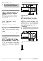
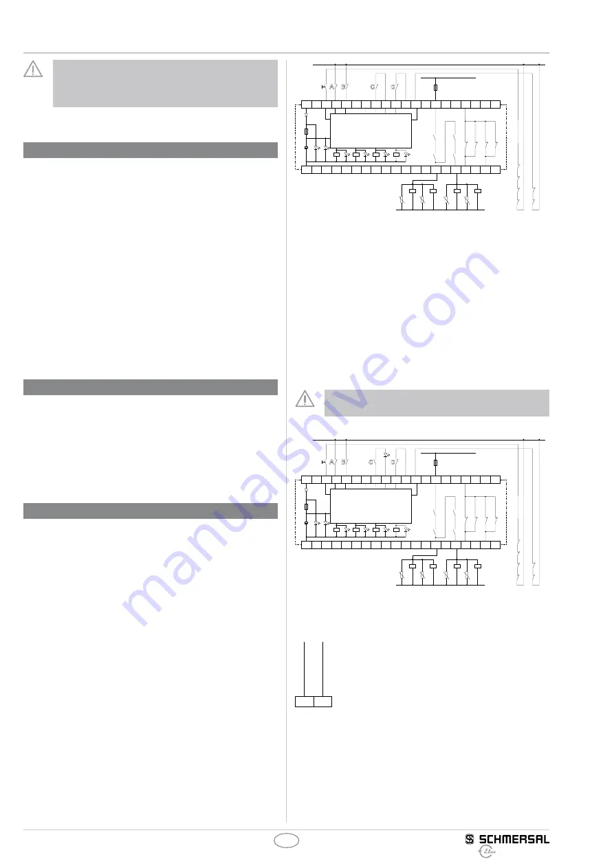
Fig. 2: SRB 202CS, 202CS/T

a) Logic

Dual-channel control, shown for a emergency stop circuit;  

with two contacts A and B and a guard door monitor with two  

contacts C and D, where at least one is a positive break contact; 

with external reset button 

J

 (related on the switch-off level 1) 

(see Fig. 3)

• Relay outputs: Suitable for 2-channel control, for increase in capacity 

or number of contacts by means of contactors or relays with positive-

guided contacts.

• 

The control system of the emergency stop circuit detects wire breakage 

and earth faults (cross-wire shorts in the SRB 202CA/QT and SRB 

202CA/Q versions). The control system of the door monitoring circuits 

detects wire breakage, earth faults and cross-wire shorts.

• 


S

 = Feedback circuit

Channel B of SRB 202CA/Q and SRB 202CA/QT: 0 V – S22 

(see Fig. 4)

L1

K1

K1

K2

K2

K3

K4

42

13

24

X2

S43

S22

S12

A1

24 VDC

J

X1

S31 S32

S44

31

14

A2

F1

UB

K

A

K

B

K

C

K

D

K

C

K

D

a)

K1

K3

K4

K2

32

K3

K4

S

K

B

N

Ui

K

A

K

C

K

D

Fig. 3: SRB 202CA, 202CA/T, SRB 202CA/Q, SRB 202CA/QT

a) Logic

S12

S22

24 VCC 0 V

Fig. 4

Due to the operating principle of the electronic fuse, the 


customer must check that no hazard is caused by an  

unexpected restart in circuits without reset button  

(automatic reset).

6  Set-up and maintenance

6.1  Functional testing

The safety function of the safety-monitoring module must be tested. 

The following conditions must be previously checked and met:

1. Correct fixing

2. Check the integrity of the cable entry and connections

3. Check the safety-monitoring module’s enclosure for damage.

4.  Check the electrical function of the connected sensors and 


their influence on the safety-monitoring module and the 


downstream actuators

6.2  Maintenance

A regular visual inspection and functional test, including the following 

steps, is recommended:

1. Check the correct fixing of the safety-monitoring module

2. Check the cable for damages

3. Check electrical function

Damaged or defective components must be replaced.

7  Disassembly and disposal

7.1  Disassembly

The safety-monitoring module must be disassembled in a de-energised 

condition only.

7.2  Disposal

The safety-monitoring module must be disposed of in an appropriate 

manner in accordance with the national prescriptions and legislations.

8  Appendix

8.1  Wiring examples

Dual-channel control, shown for a emergency stop circuit;  

with two contacts A and B and a guard door monitor with two  

contacts C and D, where at least one is a positive break contact; 

with external reset button 

J

 (related on the switch-off level 1) 

(see Fig. 2)

• Relay outputs: Suitable for 2-channel control, for increase in capacity 

or number of contacts by means of contactors or relays with positive-

guided contacts.

• 

The control system recognises wire-breakage and earth faults in the 

monitoring circuit.

• 


S

 = Feedback circuit

Summary of Contents for SRB 202CS/T

Page 1: ...ns are developed to execute safety related functions as part of an entire plant or machine It is the responsibility of the manufacturer of a machine or plant to ensure the proper functionality of the entire machinery or plant The safety monitoring module must be exclusively used in accordance with the versions listed below or for the applications authorised by the manufacturer Detailed information...

Page 2: ...the output contacts 13 14 and 13 24 meet the following requirements under observation of a B10d value assessment also refer to Requirements to DIN EN ISO 13849 1 Control category 4 PL e to DIN EN ISO 13849 1 corresponds to SIL 3 to DIN EN 61508 2 corresponds to SILCL 3 to DIN EN 62061 corresponds to control category 4 to DIN EN 954 1 To determine the Performance Level PL of the entire safety funct...

Page 3: ... 3 1 General mounting instructions Mounting snaps onto standard DIN rails to EN 60715 Snap the bottom of the enclosure slightly tilted forwards in the DIN rail and push up until it latches in position 3 2 Dimensions All measurements in mm Device dimensions H W D 100 x 22 5 x 121 mm with plugged in terminals 120 22 5 121 mm 4 Electrical connection 4 1 General information for electrical connection W...

Page 4: ...estart in circuits without reset button automatic reset 6 Set up and maintenance 6 1 Functional testing The safety function of the safety monitoring module must be tested The following conditions must be previously checked and met 1 Correct fixing 2 Check the integrity of the cable entry and connections 3 Check the safety monitoring module s enclosure for damage 4 Check the electrical function of ...

Page 5: ...ensor configuration 8 3 1 Sensor configuration superordinated switch off level 1 Single channel emergency stop circuit with command devices to DIN EN ISO 13850 EN 418 and EN 60947 5 5 Fig 8 Wire breakage and earth leakage in the control circuits are detected Dual channel emergency stop circuit with command devices to DIN EN ISO 13850 EN 418 and EN 60947 5 5 Fig 9 Wire breakage and earth leakage in...

Page 6: ...st be observed and respected 24 VDC with a max tolerance of 5 20 Otherwise availability problems could occur especially in series wired sensors where a voltage drop in the control circuit is triggered by LED s for instance 8 4 Actuator configuration Single channel control see Fig 15 Suitable for increase in capacity or number of contacts by means of contactors or relays with positive guided contac...

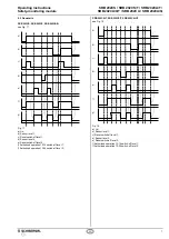
Page 7: ...c Reset switch off level 1 d Sensor level 2 e Reset switch off level 2 f Authorized operation 13 14 switch off level 1 f Authorized operation 13 24 switch off level 2 SRB 202CA T SRB 202CS T SRB 202CA QT see Fig 18 e f g d b c a Fig 18 a UB b Sensor level 1 c Reset switch off level 1 d Sensor level 2 e Reset switch off level 2 f Authorized operation 13 14 switch off level 1 f Authorized operation ...

Page 8: ...SRB 202CA T SRB 202CA QT SRB 202CA SRB 202CA Q Description of the safety component Safety monitoring module for emergency stop circuits guard door monitoring magnetic safety switches and AOPD s Harmonised EC Directives 2006 42 EC EC Machinery Directive 2004 108 EC EMC Directive Person authorized for the compilation of the technical documentation Ulrich Loss Möddinghofe 30 42279 Wuppertal Notified ...

Reviews: